


Hyamat K
8
5
Installation at site
5.1
Readiness for operation
The owner or the owner’s representative must report the
package system’s readiness for operation to the responsible
authorities (normally either the water company or the Trade
Inspection Office). Prior to commissioning, the operator must
demonstrate conclusively that the installation requirements
have been complied with.
Prior to connecting the package unit to the mains, the user must
have familiarized himself with the relevant VDE standards.
The power supply line must be installed / connected by a duly
authorized company.
5.2
Installation and location as per DIN 1988
The Hyamat must be located either in the control room or in a
well-ventilated, frost-free, lockable room used for no other
purpose. No harmful gases are allowed to enter the place of
installation. An adequately sized drain connection (leading to a
sewer or equivalent) must be provided.
The unit is designed for a maximum ambient temperature of
0
˚
C to +40
˚
C at a relative air humidity of 50 %.
Hyamat units should not be installed next to sleeping or living
quarters.
Thanks to the anti-vibration mounting buffers, the Hyamat unit
is adequately insulated to prevent transmission of solid-borne
noise.
To reduce the motor sound emission, we offer acoustic cladding
as an accessory. If expansion joints (see Accessories) are used
for damping vibrations, their fatigue strength (endurance limit)
must be given due consideration. They must be installed for
quick and easy replacement.
5.3
Piping
All piping must be installed without transmitting any stresses or
strains. The use of length-limited expansion joints is advisable
(see Accessories).
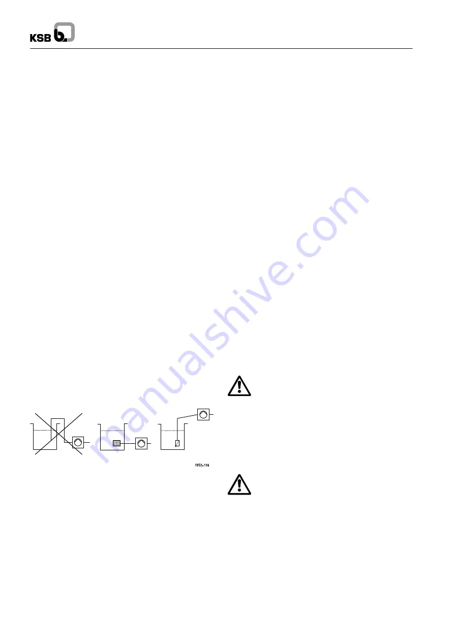
The formation of air pockets must be avoided. For suction lift
operation, the suction side piping must be laid with a
continuously rising slope.
Incorrect
Correct
Suction lift operation
5.4
Foundation
The package system is designed for installation on a level
concrete floor. Its anti-vibration pads provide adequate
insulation against solid-borne noise.
Thanks to level-adjustable mounting feet (see Accessories) the
system can also be installed in horizontal position on uneven
floors.
Units with Movitec 32, 45 or 65 pump are supplied with
level-adjustable feet. 2 of these feet can be fixed to the floor.
5.5
Installation
Prior to installing the system, remove the packaging.
Connect the system’s inlet and discharge pressure lines with
the corresponding distribution lines (DIN 1988).
In order to avoid transmission of piping forces onto the system
and transmission of solid-borne noise, we recommend
installing length-limited expansion joints.
The unit must be accessible to allow maintenance and repair
work.
Units with Movitec 32, 45 or 65 pumps are supplied with
additional, ajdustable anti-vibration expansion joints. Two of
these expansion joints can be fixed to the floor to compensate
the axial thrust.
Adjustable anti-vibration expansion joints are available on
option for units equipped with Movitec 2, 4, 10 or 18.
5.6
Acoustic cladding (supplementary
equipment)
Acoustic cladding reduces the air-borne sound caused by
motors. The cooling air inlets must remain unobstructed.
Sufficient circulation must be ensured.
5.7
Installing an expansion joint
The expansion joint must have a length limiter with solid-borne
sound insulation so as to be able to absorb reaction forces. The
expansion joint must be installed in the piping free of twist. It
must not be used to compensate for misalignment or mismatch
of the piping. During assembly, the bolts must be evenly
tightened crosswise. The ends of the bolts must not protrude
from the flange. If any welding work is carried out nearby, the
expansion joint must be covered for protection (spark, radiant
heat). The expansion joint must remain unpainted and shall not
be allowed to come into contact with oil. Its position within the
system must allow easy access and inspection and, therefore,
it must not be insulated along with the piping.
Expansion joints are subject to wear. Consequently,
the expansion joint must be checked at regular
intervals for early detection of cracking or bubbling,
exposed
fabric
or
other
defects
(see
recommendations laid down in DIN 1988).
5.8
Installing a pressure reducer
A length of approximately 600 mm must be provided on the inlet
pressure side to accommodate a pressure reducer, if necessary.
A pressure reducer must be installed if the inlet
pressure fluctuation is so high that the system must be
shut down or if the total system pressure (inlet
pressure plus shutoff head) exceeds the design
pressure.
The maximum pump discharge pressure at shutoff head is
reached in manual mode.
For the pressure reducer to function properly, there must be a
minimum pressure gradient of 5 m. The pressure downstream
of the pressure reducer (downstream pressure) is the basic
parameter for determining the pump head.
Summary of Contents for Hyamat K 0202
Page 2: ...Hyamat K 2...
Page 27: ...Hyamat K 27...


