


Page 3
Copyright © 2009 GEBEL Aquasafe. • All Rights Reserved • May 2010 • Pub. No. MAN 200
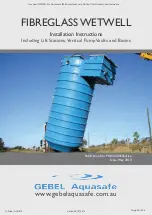
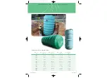
FIBREGLASS WETWELL INSTALLATION
!
!
BEFORE YOU BEGIN
• Read, understand and follow these instructions.
• Barricade the work area.
• Review and prepare to complete the installation checklist as
the installation progresses.
If you have questions on other wetwell installation details, call
Technical Support at 02 4722 9696
A. HANDLING AND PREPARATION
WARNING
Do not stand on or under wetwell while it is being lifted. This
could result in personal injury or death.
• Do not drop or impact the wetwell.
• Wetwells should be stored horizontally and chocked, using
only appropriate materials such as sandbags, tires, or other soft
or pliable materials.
• Upon wetwell delivery and when lifting wetwell, visually
inspect entire exterior surface of the wetwell for shipping or
handling damage.
• If the wetwell must be moved by rolling, ensure that ground
to be traversed is smooth and free of rocks, debris, or other
hard objects.
• Do not roll or set the wetwell on any pipe stubout, acces
-
sory or appurtenance installed on the wetwell.
• The contractor is responsible for rigging, unloading and se
-
curing the wetwell.
• When lifting the wetwell in the horizontal position, use two
slings with a spreader bar.
• Use a minimum of two lift lugs when pivoting the wetwell
from horizontal to vertical.
• Utilize all lift lugs provided at the wetwell top for vertical
lifting.
• Only a pliable strap or rope should contact the wetwell, do
not use chains, steel cables or hard metallic slings.
B. SITE PREPARATION
Dimensions of the excavation should be wide enough to pro
-
vide sufficient working room around the wetwell.
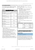
Minimum anti floatation ring and ballast dimensions are speci
-
fied in (Table 1, page 7)
Anti floatation ring and ballast designs in (Table 1, page 7) meet
Australian Standard Code S3600A.
(Dead load resisting floatation have a factor of safety of
0.9 applied.)
!
C. ANTI FLOTATION BALLAST FRP
WETWELLS
WARNING
Collapsing excavation walls can cause injury or death. Do not
enter the wetwell excavation unless necessary and in compliance
with OHS regulations. Follow OHS guidelines for excavations.
WETWELLS
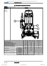
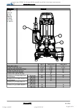
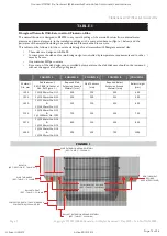
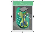
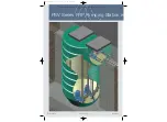
• Lower Wetwell onto Compacted Base then place Wet con
-
crete around the Unit covers 2 x Ribs plus meets the Ballast
Quantity in (Table 1 and figure 1, page 7.)
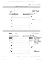
Cold concrete joints are not allowed. Fibreglass solid bot
-
tom wetwells with external reinforcing ribs must be installed
in a continuous and monolithic concrete pour. Concrete must
extend 75mm above the second rib from the wetwell bottom,
and around the entire circumference of the wetwell. (Refer to
figure 1, page 7)
• Concrete slab must fill all gaps and voids in and around the
external tank reinforcing ribs.
• It may be necessary to add ballast (water) inside the wetwell
to counteract buoyancy until the concrete is cured.
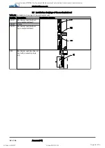
ANTI FLOATATION RING CONCRETE SLAB
Use minimum 20 mpa concrete for anti floatation and ballast
Final concrete depth, size, thickness and reinforcements
shall meet the minimum requirements in these instructions
and applicable tables. Anti floatation ring should extend a
minimum of (refer to table 1, page 7) in all directions from the
wetwell outer diameter.
CAUTION
Voids in the concrete slab around external structural anchors will
result in product damage and environmental contamination.
Goodnal STP ST041 Pre Treatment (KSB Amenities Pump Station OM Manual) Vendor Manual
Q-Pulse Id VM372
Active 29/10/2013
Page 71 of 94


