background image

6 Operation

16 of 28

4EYS / 4EYT

1974.91/01-EN

6 Operation

6.1 Safety instructions for operation

CAUTION

Air intake via the seal faces

Dry running of the seal and consequential seal failure!

For single seals the pressure in the seal chamber of the pump must always be
higher than the ambient pressure.

CAUTION

Unsuitable fluid to be sealed off

Damage to the machinery!

Take appropriate measures to ensure that the fluid to be sealed off at the
mechanical seal is in liquid condition no matter what the operating status of
the pump. This applies in particular when starting up and stopping the pump.

If the fluid to be sealed off forms deposits while the pump set cools down or
during standstill of the pump set, the seal chamber must be flushed through
with a clean liquid. The quantity and type of flushing liquid has to be defined
by the operator for the specific material combination of the mechanical seal.

CAUTION

Excessive rise in temperature

Damage to the mechanical seal!

Dry running or damage to the elastomers, incrustations at the seal faces, etc.

Shut down the pump as described in the operating manual.

NOTE

If the operating limits indicated are observed and the instructions given in this
manual are complied with, the mechanical seal can be expected to give trouble-free
operation. If the values during operation are not within the specified limits, the
mechanical seal must be removed from the system and sent to KSB for inspection.

6.2 Emissions

 WARNING

Incorrect handling of the fluid to be sealed off

Risk of injury!

If the fluid to be sealed off and/or the buffer fluid have to meet the
requirements of the German Hazardous Substances Regulations, the regulations
on handling hazardous substances (safety data sheets to Directive 91/155/EEC)
and the accident prevention regulations must be heeded.

NOTE

If a reduction in leakage cannot be observed or if other failures occur, the
mechanical seal must be shut down, removed from the system and sent to KSB for
inspection.

Summary of Contents for 4EYS

Page 1: ...KSB Mechanical Seal 4EYS 4EYT Installation Operating Manual...

Page 2: ...nts provided herein must neither be distributed copied reproduced edited or processed for any other purpose nor otherwise transmitted published or made available to a third party without the manufactu...

Page 3: ...sport 8 3 3 Storage preservation 8 3 4 Return to supplier 9 3 5 Disposal 10 4 Description 11 4 1 General description 11 4 2 Designation 11 4 3 Materials 11 4 4 Design details 11 4 5 Configuration and...

Page 4: ...hnical personnel 1 3 Other applicable documents Table 1 Overview of other applicable documents Document Contents Data sheet Description of the technical data of the pump set in which the mechanical se...

Page 5: ...us injury Electrical hazard In conjunction with one of the signal words this symbol indicates a hazard involving electrical voltage and identifies information about protection against electrical volta...

Page 6: ...ty cover and of any and all rights to claims for damages Non compliance can for example have the following consequences Hazards to persons due to electrical thermal mechanical and chemical effects and...

Page 7: ...ambient temperature Pump pressure must have been released and the pump must have been drained When taking the pump set out of service always adhere to the procedure described in the manual Decontamina...

Page 8: ...ontractual agreement CAUTION Removing transport locks too early Damage to previously locked components during transport If transport locks are fitted do not remove them too early 3 3 Storage preservat...

Page 9: ...ree and vermin free If properly stored indoors the equipment is protected for a maximum of 36 months New mechanical seals are supplied by our factory duly prepared for storage 3 4 Return to supplier 1...

Page 10: ...fluid and any fluid residues Wear safety clothing and a protective mask if required Observe all legal regulations on the disposal of fluids posing a health hazard 1 Dismantle the mechanical seal Colle...

Page 11: ...ingle spring L Direction of rotation anti clockwise R Direction of rotation clockwise 0 Anti twist lock of mating ring 0 Without lock 1 With lock 4EYS Type series type 4EYS Overall length N specially...

Page 12: ...1 by springs 9 O rings 5 and 6 are fitted for secondary sealing On type series 4EYT thrust ring 7 engages with primary ring 2 and torque transmitting element 8 forcing them to rotate with the shaft w...

Page 13: ...rease Kl ber Asonic HQ 72 102 are used for elastomers that do not serve to transmit the torque Examples are mating rings with an anti twist lock or primary rings that move axially relative to the pump...

Page 14: ...ling the mechanical seal The mechanical seal and assembly aids are on hand The relevant documentation for installing the mechanical seal is being observed The back pull out unit has been removed from...

Page 15: ...tion of the installation work The operating manual for the pump is on hand The mechanical seal is accessible The components have been placed down and secured in a horizontal position NOTE If any disma...

Page 16: ...he mechanical seal CAUTION Excessive rise in temperature Damage to the mechanical seal Dry running or damage to the elastomers incrustations at the seal faces etc Shut down the pump as described in th...

Page 17: ...documents NOTE The following values are limits that depend on the seal face materials and elastomer materials As the characteristics influence each other operation at minimum maximum limits is not po...

Page 18: ...operation includes regular checks of the temperature and leakage drainage and of the mechanical seal s buffer fluid pressure and fill level When a system maintenance inspection or pump maintenance ins...

Page 19: ...ghts to claims for damages NOTE For any failures you cannot remedy or whose cause cannot be identified contact the responsible KSB service centre What to do in the event of a failure Determine and doc...

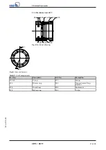
Page 20: ...seal 4EYS 475 472 900 904 412 52 412 53 474 477 550 485 Fig 3 Sectional view left A A right B B B A B A Fig 4 Cross section axis Table 8 List of components Part No Description Part No Description 412...

Page 21: ...485 472 475 932 474 477 412 53 Fig 5 Sectional drawing A A Fig 6 Cross section axis Table 9 List of components Part No Description Part No Description 412 53 O ring 477 Spring 472 Primary ring 485 Tor...

Page 22: ...10 2 5 52 5 033 47 42 48 16 55 45 10 2 5 56 5 048 64 59 66 16 5 60 48 5 11 5 2 6 63 5 5 To determine the safety distance between rotating and stationary components these dimensions are recommended as...

Page 23: ...34 7 To determine the safety distance between rotating and stationary components these dimensions are recommended as maximum dimensions 8 The mechanical seal manufacturer may supply a mechanical seal...

Page 24: ...bearing ring carrier plain bearing inner rotor has been removed from the pump and cleaned In cases of containment shroud leakage the outer rotor bearing bracket lantern leakage barrier and bearing bra...

Page 25: ...11 Designation 11 Disposal 10 E Event of damage 4 K Key to safety symbols markings 5 O Other applicable documents 4 P Personnel 6 Q Qualification 6 R Return to supplier 9 S Safety 5 Safety awareness 6...

Page 26: ......

Page 27: ......
Page 28: ...KSB SE Co KGaA Johann Klein Stra e 9 67227 Frankenthal Germany Tel 49 6233 86 0 www ksb com 1974 91 01 EN 05069122...

Reviews: