ENGLISH
23
M1157-3_draft-0
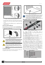
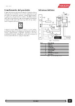
Operating principle
Pic.1 –
Main components
The appliance uses a fan (5) to suck up the air (14) to be dehu-
midified and pass it through the refrigerator circuit evaporator
(9). In this way the temperature of the air is lowered to below its
dew point and the vapour condenses to form drops of water that
are collected in the appropriate tank (11).
The condensate water is NOT drinkable. Do NOT
drink this water anyway.
The air thus dehumidified is passed through the condenser (10)
that raises its temperature slightly higher than the initial value. In
this way the quantity of humidity contained in the environmen-
tal air is gradually decreased until it reaches the desired value.
When the dehumidifier works in a room it reduces
the humidity of the walls and floor of the room, as
well as in the materials contained therein.
The defrosting cycle
If the temperature goes below 16°C ice may form on the evapo-
rator (9). The ice must be regularly melted to prevent it from
reducing the air passage. The electronic board automatically
performs the defrosting cycle (see ahead). During the defrosting
cycle the compressor (6) stops. The time it takes to melt the ice
changes with the humidity and temperature.
Installation
For correct installation, follow the series of operations described
below.
Handling
Before installation it is advisable to bring the packed dehumidi-
fier as close as possible to the place where it will be mounted.
CAUTION: The size and the weight of the machine
require the aid of means such as pallet trucks and
trolleys for handling. NEVER lift the machine alone.
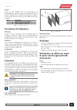
Placement
Pic.2 –
Positioning and minimum distances
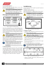
Wall installation
• Use the bracket as a template to mark the holes on the wall as
shown in Pic.3.
Make sure that the wall is able to support the device
in operating conditions.
• Drill on the wall n.3 holes Ø10mm, 65mm deep as shown in
Pic.3. Alternatively, you can apply smaller screws (not sup-
plied) using the four Ø5 holes.
• Clean the inside of the holes.
• Insert the three supplied expansion plugs holding in vertical
position the expansion tabs.
• Secure the bracket using the three screws supplied.
To respect the minimum distance of 0,5 meters from
the bottom (Pic.2) drill the holes to at least 0.8 meters
from the floor.
Pic.3 –
The wall bracket
• Lift the machine and hook the rear bracket S to M bracket
mounted on the wall.
Pic.4 –
Placement of the dehumidifier on the wall.
Summary of Contents for KRK 160
Page 2: ...2 M1157 3_draft 0 ...
Page 3: ...3 M1157 3_draft 0 ...
Page 4: ...4 M1157 3_draft 0 ...
Page 5: ...5 M1157 3_draft 0 ...
Page 11: ...11 M1157 3_draft 0 ...
Page 27: ...27 M1157 3_draft 0 ...
Page 28: ......

