40
7.5 SQUEEGEE ASSEMBLY
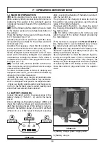
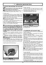
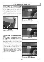
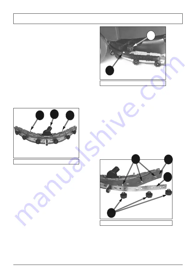
Put the two fixing pins of the squeegee ( Photo 23
- A ) inside the holes in the squeegee support (
Photo 22 - A ).
Screw the two knobs ( Photo 22 - B ) in order to se-
cure the squeegee to the support ( Photo 22 - A ).
Connect the suction hose coming from the ma-
chine to the suction coupling pipe on the squeegee
body ( Photo 23 - B ).
7.6 SQUEEGEE DISASSEMBLY
Disconnect the suction hose from the coupling pipe
on the squeegee body ( Photo 23 - B ).
Unscrew the two knobs ( Photo 22 - B ) that secure
the squeegee to its support and push down the
squeegee to free it.
7 - OPERATING INFORMATIONS
7.7 SQUEEGEE BLADES DISASSEMBLY / AS-
SEMBLY
Disassemble the squeegee from its support ( see
7.5).
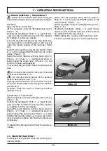
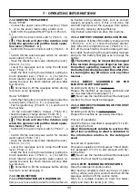
Unscrew the knobs ( Photo 24 - A ) and remove
metal blade retainer ( Photo 24 - B )
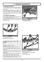
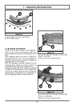
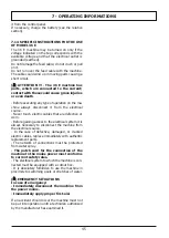
Extract the fixing bolts ( Photo 24 - C ) and remove
the front metal blade retainer ( Photo 25 - A );
remove the squeegee rubber blades tearing them
from a side.
To replace the squeegee rubber blades, follow the
same procedure on the contrary starting from the
front blade;
lock the fixing bolts ( Photo 24 - C ) retaining them
in the squared seats in the squeegee body;
then, place the rear rubber blade ( Photo 24 - D )
and the metal blade retainer ( Photo 24 - B ), loc-
king them with the fixing knobs ( Photo 24 - A ).
B
A
A
B
C
D
Photo 22
Photo 23
Photo 24
B
A
A) Squeegee support
B) Squeegee fixing knob
A) Squeegee fixing pin
B) Suction hose coupling pipe
A) Squeegee fixing knob
B) Metal retainer for rubber blades
C) Fixing bolts
D) Rear rubber blade
A

