GB-12
D
GB
F
NL
I
E
Assistance in the event of
malfunction
DANGER
Electric shocks can be fatal! Before working on
possible live components, ensure the unit is discon-
nected from the power supply.
Risk of injury! Burner heads have sharp edges.
Fault-clearance must only be undertaken by author-
ized trained personnel.
▷
If no fault is detected when checking the burner,
proceed to the automatic burner control unit and
check for faults in accordance with the relevant
operating instructions.
?
Faults
!
Cause
•
Remedy
?
Burner does not function?
!
Valves do not open.
•
Check the voltage supply and wiring.
!
Tightness control signals a fault.
•
Check the valves for tightness.
•
Note the tightness control operating instructions.
!
Control valves do not move to low-fire position.
•
Check the impulse lines.
!
Gas inlet pressure is too low.
•
Check the filter for dirt.
!
Gas and air pressures on the burner are too low.
•
Check the restrictors.
!
Automatic burner control unit signals a fault.
•
Check the ionization cables and ionization cur-
rent.
•
Check whether the burner is adequately
grounded.
•
Note the automatic burner control unit operating
instructions.
?
Burner performs a fault lock-out after burn-
ing faultlessly in normal operation?
!
Incorrect gas and air flow rate settings.
•
Check the gas and air pressures.
!
No ignition spark is created.
•
Check the ignition cable.
•
Check the voltage supply and wiring.
•
Check whether the burner is adequately
grounded.
•
Check the electrodes – see page 10 (Checking
the ignition and ionization electrodes).
!
Automatic burner control unit signals a fault.
•
Check the ionization cable.
•
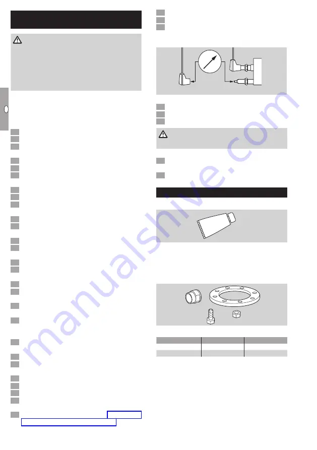
Measure the ionization current by connecting a
micro-ammeter into the ionization cable: min.
5 µA ionization current – stable signal.
+
μ
A
–
Z
I
!
Burner head dirty.
•
Clean gas and air bore holes and air slots.
•
Remove deposits on the burner head.
WARNING
Risk of injury! Burner heads have sharp edges.
!
Excessive pressure fluctuations in the furnace
chamber.
•
Ask Elster Kromschröder for control concepts.
Accessories
Ceramic paste
Apply ceramic paste to the relevant screw connec-
tions after replacing any burner components in order
to avoid cold-setting.
Order number: 05012009.
Adapter set
8×
8×
For connecting ZIC to NPT/ANSI connections.
Burner
Adapter set
Order No.
ZIC 165
BR 165 NPT
74922636
ZIC 200
BR 200 NPT
74922637
Nozzle set
▷
Available on request for connecting integrated
ignition lances to NPT threads.


