


3
ELECTRICAL CONNECTIONS
20
OPTIWAVE X400
www.krohne.com
06/2021 - 4006413503 - AD NEPSI OPTIWAVE x400 R03 en
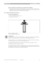
•
3-mm Allen wrench (not supplied)
•
Attach the cover. Make sure that a slot on the top of the cover is correctly aligned with the hole
for the cover stop.
•
Attach the cover stop (make sure that there is also a spring washer and a socket head screw).
Tighten the screw with a 3-mm Allen wrench.
3.3 Terminal tightening capacity
The terminal tightening capacity of input/output terminals is:
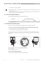
3.4 Equipotential bonding system
Connect the device to the equipotential bonding system for the hazardous location.
You can use 2 terminals to connect the device to the equipotential bonding system:
•
a ground connection in the terminal compartment and
•
an external ground terminal adjacent to the cable entries
You can also use the process connection to connect the device to the equipotential bonding
system. Make sure that there is a good electrical connection to the process connection (flange,
thread etc.).
Ex ia- and Ex iaD-approved devices
The device electronics are isolated with a rating of 500 V
RMS
.
Type of wire
Terminal tightening capacity
[mm
²
]
[AWG]
Flexible or rigid
2.5
13
Figure 3-3: Examples of terminals for the equipotential bonding system
1
Internal terminal
2
External terminal (on the housing)


