10
English
AS 72 S
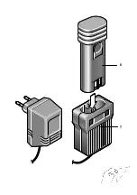
Battery charging unit type: A 30950 G
Use as Intended
The device is only designed for charging Kress NiCd
batteries with a voltage of 7.2 V
Charging Procedure
The charger is suitable for mounting on the wall.
The charging process begins as soon as the mains
plug is inserted into the power supply socket and the
battery is placed into battery charger slot.
The maximum charging time is 4 hours, but if there is
already a residual charge available, the charging time
is respectively shorter.
After a maximum charging time of 8 hours, the battery
should be disconnected from the battery charger or
removed from the charger adapter.
If the batteries cannot be charged correctly:
1. Make sure the socket is providing voltage.
2. Make sure the charging points provide good
contact.
3. Should charging still not be possible, please send
the battery and battery charger to our nearest serv-
ice centre.
Notes for the correct use of the battery:
– To obtain the maximum service life, do not
recharge the battery immediately after a short
period of use but, if possible, discharge to the lower
capacity limit and then recharge.
– Avoid to the extent possible the blocking of the
machine. The resulting excessive current flow
leads to quick discharging and increased wear of
the battery.
– An increasingly shorter operating time per recharg-
ing of the battery is an indication that the battery is
worn out and must be replaced.
Do not carry out any repair on the charger yourself!
As a basic rule, return the faulty machine to our next
customer service centre (also in the case of defective
mains cables)!
Convince yourself before using that the battery is
securely seated in the machine.
Switching On/Off
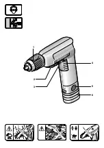
Press or release the on/off switch
4
.
Rotational direction switch
The rotational direction of the working spindle is set
using the rotational direction switch
3
.
Right: Press the rotational direction switch to posi-
tion “R”.
Left:
Press the rotational direction switch to posi-
tion “L”.
In the central position (“Lock”) the ON/OFF switch is
blocked. The machine is thereby prevented from
being switch on unintentionally and the battery is pro-
tected against unintended discharging. In addition,
the working spindle is locked when the switch is in this
position. This enables a tool or bit to be changed, or
the drill chuck to be mounted or dismounted.
In the “Lock” position the battery-driven screwdriver
can also be used for manual screw-driving jobs that
are beyond the capacity of the screwdriver (e. g.
unscrewing tightly lodged, rusty screws).
Attention! Change direction of rotation only when
the motor has ceased turning!
Operation of the Quick Clamping Drill Chuck
Rotational direction switch in the LOCK
position
p
.
The fully automatic spindle locking makes possible
quick and easy changing of the tool in the drill chuck.
Opening:
Turn the sleeve in the “AUF” direction.
Clamping: Open the chuck and insert the tool as far
as possible.
Firmly clamp the chuck by turning the
sleeve in the “ZU” direction.
For soft drill shafts, it may be necessary to retighten
after a short time.
Caution! For reasons of safety, take the bat-
tery out of the device for all installation and
removal operations!
7 Putting into Operation
Summary of Contents for 12 04 0519
Page 2: ...7 6 ...
Page 3: ...6 1 2 3 4 5 ...


