background image

13

Pic.6.2.5

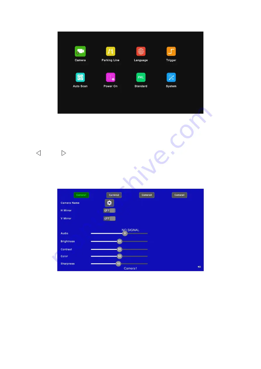
6.2.5.1 Camera

IR Instructions:

VOL/ VOL : Move the cursor to switch camera input or increase / decrease volume.

● SEL: Select camera input.
● UP / DOWN: Switch and move the cursor.
● MENU: Return to the previous menu.

Pic.6.2.5.1

Features Instructions:
● Camera Name: Camera channel name.
● H Mirror: Horizontal mirror.
● V Mirror: Vertical mirror.
● Audio: Volume of the camera channel. Each camera channel has its own volume setting (when

under mute mode, the operation of Audio adjustment will cancel the mute).

● Brightness: Brightness of the image.

Summary of Contents for 5609179185386

Page 1: ...plexer Please read all instructions before using the product and keep the manual for future reference The product may differ from the manual description according to the upgraded S W version or perfor...

Page 2: ...peration Functional Specification 7 6 1 IR Remote Control 7 6 2 Menu Operation 7 6 2 1 Desktop 9 6 2 2 Home Menu 9 6 2 3 Volume 10 6 2 4 Mode 10 6 2 5 Setting 12 6 2 5 1 Camera 13 6 2 5 2 Parking Line...

Page 3: ...ulation around the device Operating Precautions 1 The device can be powered by DC power 10V 32V e g 12V or 24V ACC 2 Make sure all cables are connected properly and check the polarity as improper cabl...

Page 4: ...bol is intended to alert the user to the presence of uninsulated dangerous voltage within the product s enclosure that may be of sufficient magnitude to constitute risk of electric shock to persons Th...

Page 5: ...age adjustment for horizontal mirror vertical mirror view display 6 Four trigger wires with trigger display image delay and priority adjustable 7 Support auto scanning with scanning sequence and durat...

Page 6: ...ccessories Power cable Camera input cable Video output Trigger cable IR Remote control IR extension cable Video magnification line Special Notice Accessories may be different for corresponding applica...

Page 7: ...ication IR Remote Control Receiver Indicator PWR Power Status CHx Camera Input Status RUN Error Status IR Extension Cable Connector Camera Input Connector Debug DC Power Input Connector Video Output T...

Page 8: ...ctor with label Right CAM to camera 2 3 Connect 4Pin male connector with label Front CAM to camera 3 4 Connect 4Pin male connector with label Rear CAM to camera 4 Video output Trigger cable 1 Connect...

Page 9: ...adjustment menu Move the red box in the magnified mode Move the displayed place of the magnified image Move the menu cursor Pic 6 1 Move up the menu cursor Mute or unmute N A Move left the menu curso...

Page 10: ...box if the red box is shown in the magnified mode LANG Switch to different languages on some menus REST Reset the system AV Magnify the red box if the red box is shown in the magnified mode SEL Enter...

Page 11: ...AL CAM4 CAM3 CAM2 CAM1 PIP3 PIP2 PIP1 QUAD If user press DN key it will be switched in the opposite order Other Instructions When the device is in single view display and not in special mode like auto...

Page 12: ...10 Pic 6 2 2 6 2 3 Volume Menu IR Instructions VOL or VOL Decrease or increase volume MUTE Mute or unmute the multiplexer MENU Return to the previous menu Pic 6 2 3 6 2 4 Mode Menu...

Page 13: ...iew display mode MENU Return to the previous menu Pic 6 2 4 6 2 4 1 Split Setup Menu IR Instructions VOL VOL To change the corresponding features of the layer when setting up Layer 1 4 to move the cur...

Page 14: ...play mode Width Scale Ratio The horizontal down scale ratio of the layer Height Scale Ratio The vertical down scale ratio of the layer X Position Type The horizontal position of the layer Y Position T...

Page 15: ...move the cursor MENU Return to the previous menu Pic 6 2 5 1 Features Instructions Camera Name Camera channel name H Mirror Horizontal mirror V Mirror Vertical mirror Audio Volume of the camera chann...

Page 16: ...1 special numerical character 2 capital letters low case letters RESET Delete characters when editing Pic 6 2 5 1 1 Other Instructions Following keys are special for 1 Caps Switch between capital low...

Page 17: ...he parking line P N Switch the parking line focuses RESET Return to the default configuration AV Switch parking line types MENU Return to the previous menu Pic 6 2 5 2 1 6 2 5 3 Language IR Instructio...

Page 18: ...Delay Image display will last for a few seconds 0 60s after trigger signal disappears Priority Settings of trigger priorities Trigger in higher priority has priority over trigger in lower priority The...

Page 19: ...number MENU Return to the previous menu without saving Pic 6 2 5 4 1 Other Instructions Input number will turn to 60 if it is larger than 60 Enter Save input Number input in Delay will be saved if re...

Page 20: ...Instructions Display to set preferred display image when in auto scanning Please refer to part 6 2 5 4 3 Display for details Delay To set duration time of scanning image ranging 0 60s Operation of del...

Page 21: ...SEL Highlight cancel highlight the icon selected MENU Return to the previous menu and save Pic 6 2 5 6 Other Instructions Highlighted icon is corresponding display image of multiplexer upon start up...

Page 22: ...s turned ON multiplexer will adjust camera display automatically In this case system setting in CAMERA 1 CAMERA 4 and auto configuration of Automatic won t work When Automatic is turned OFF multiplexe...

Page 23: ...ructions Menu Lock Degree of menu lock There are 3 levels of menu lock 1 LEVEL1 All buttons fail to response 2 LELVE2 All buttons fail to response except for POWER VOL or VOL 3 LEVEL3 No response to M...

Reviews: