background image

41

Manual

www.kraun.it

4.5.1  ACL

Choose “

Access Management

ACL

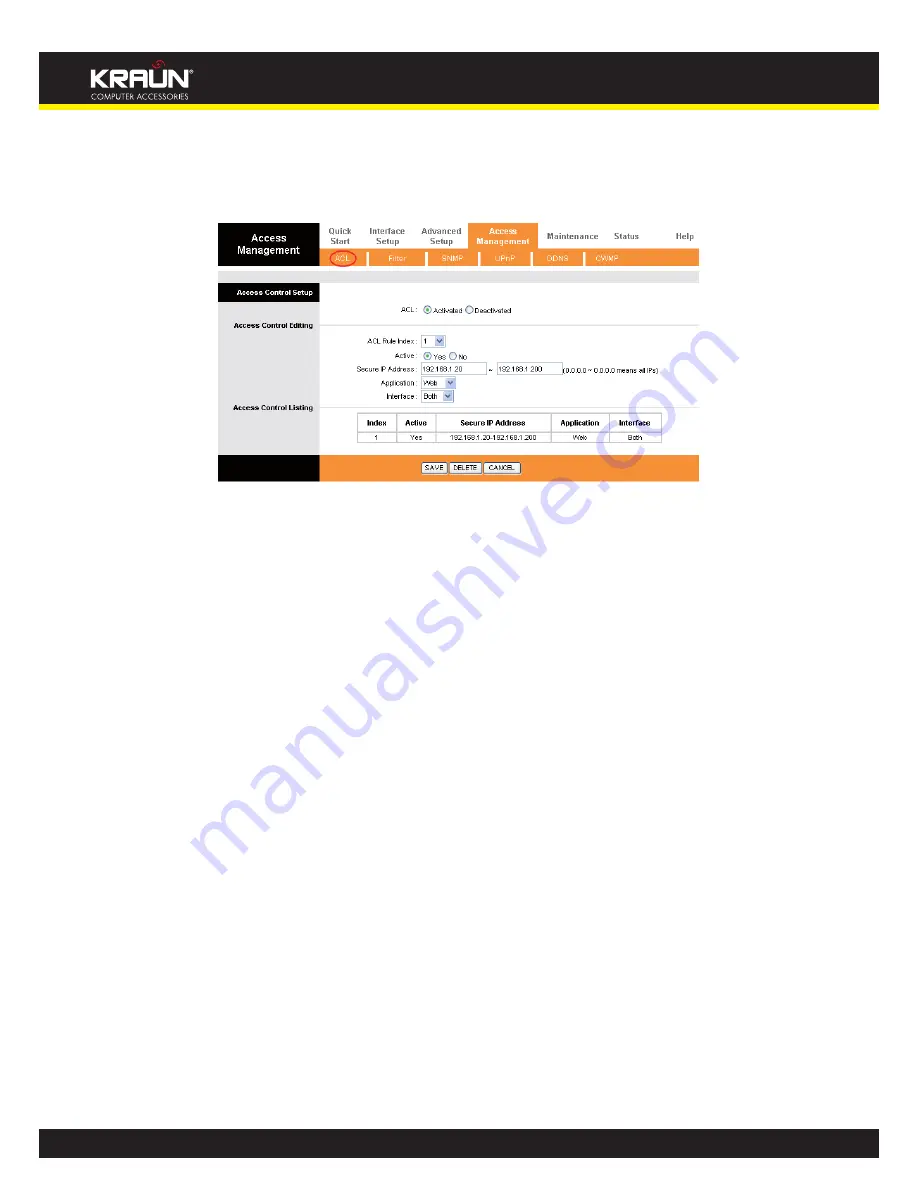
”, you can see the next screen (shown in Figure 4-38). You can specify the 

client to access the ADSL Router once setting his IP as a Secure IP Address through selected applications.

Figure 4-38


y

ACL: 

If 

Activated

, the IP addresses which are contained in the Access Control List can access to the Router. If 

Deactivated

, all IP addresses can access to the Router.


y

ACL Rule Index:

 Select the ACL rule index for the entry. 


y

Active:

 Enable the ACL rule.


y

Secure IP Address:

 Select the IP addresses which are permitted to access to the Router remotely. With the 

default IP 0.0.0.0, any client would be allowed to remotely access the ADSL Router.


y

Application:

 Select the application for the ACL rule, and then you can access the Router through it.


y

Interface:

 Select the interface for access: LAN, WAN or Both.


y

Access Control of Listing:

 This displays the information about the ACL Rules.

4.5.2  Filter

Choose “

Access Management

Filter

”, you can see the Filter screen (the default is IP/MAC Filter screen shown 

in Figure 4-39 ). The filtering feature includes IP/MAC Filter, Application Filter, and URL Filter. The feature makes 

it possible for administrators to control user’s access to the Internet, protect the networks.

4.5.2.1  IP Filter

Select 

IP/Mac Filter

 as the Filter type, and select 

IP

 as the Rule type (shown in Figure 4-39), then you can config-

ure the filter rules based on IP address. The filtering includes 

Outgoing 

and

 Incoming

, the detailed descriptions 

are provided below.

Summary of Contents for Wireless ADSL2/2plus Modem Router 54Mbps

Page 1: ...nufacturer is under no circumstances liable for any unauthorised modifications made to the product by the user or any other parties which may compromise its conformity and safety Cod KN 3N User s Manual ADSL2 2 Wireless N Router 300Mbps ...

Page 2: ...ation Guide 9 3 1 Configure PC 9 3 2 Login 12 Chapter 4 Software Configuration 15 4 1 Status 15 4 1 1 Device Info 15 4 1 2 System Log 16 4 1 3 Statistics 16 4 2 Quick Start 18 4 3 Interface Setup 18 4 3 1 Internet 19 Dynamic IP Address 20 Static IP Address 21 PPPoA PPPoE 22 Bridge Mode 23 4 3 2 LAN 24 4 3 3 Wireless 26 WEP 64Bits 28 WEP 128Bits 28 WPA PSK 28 WPA2 PSK 29 WPA PSK WPA2 PSK 29 4 4 Adv...

Page 3: ... 2 1 IP Filter 41 4 5 2 2 MAC Filter 45 4 5 2 3 Application Filter 47 4 5 2 4 URL 47 4 5 3 SNMP 48 4 5 4 UPnP 49 4 5 5 DDNS 49 4 5 6 CWMP 50 4 6 Maintenance 51 4 6 1 Administration 51 4 6 2 Time Zone 51 NTP Server automatically 52 PC s Clock 52 Manually 53 4 6 3 Firmware 53 4 6 4 System Restart 55 4 6 5 Diagnostic 55 4 7 Help 56 Chapter 5 Appendix A Specifications 57 ...

Page 4: ...onnected to the Internet using a single Wide Area Network WAN interface and single global IP address The advanced security enhancements IP MAC Filter Application Filter and URL Filter can help to protect your network from potentially devastating intrusions by malicious agents from the outside of your network Quick Start of the Web based Utility is supplied and friendly help messages are provided f...

Page 5: ...width y y Supports All ADSL industrial standards y y Compatible with all mainstream DSLAM CO y y Provides integrated access of internet and route function which face to SOHO user y y Real time Configuration and device monitoring y y Supports Multiple PVC Permanent Virtual Circuit y y Built in DHCP server y y Built in firewall supporting IP MAC filter Application filter and URL filter y y Supports ...

Page 6: ...Internet WLAN On The wireless function is enabled but no data is being transmitted Flash There is wireless data being transmitted Off The wireless function is disabled LAN 1 4 Flash Data is being transferred over the 1 4 LAN port On There is a successful connection on the corresponding 1 4 LAN port but no activity Off There is no connection on the corresponding 1 4 LAN port or the connection is ab...

Page 7: ... SysRestart of the Router s Web based Utility y y LINE Through the port you can connect the router with the telephone Or you can connect them by an external separate splitter For details please refer to 2 4 y y Antenna Used for wireless operation and data transmit 2 3 Installation Environment y y The Product should not be located where it will be exposed to moisture or excessive heat y y Place the...

Page 8: ...ce and then you can access the Internet and make calls at the same time The external splitter has three ports LINE Connect to the wall jack PHONE Connect to the phone sets MODEM Connect to the ADSL LINE port of Kraun 300N Plug one end of the twisted pair ADSL cable into the ADSL LINE port on the rear panel of Kraun 300N Connect the other end to the MODEM port of the external splitter Step 2 Connec...

Page 9: ...er to a Hub Switch which has con nected to the Router you need to configure your PC s IP address Follow the steps below to configure it Step 1 Click the Start menu on your desktop right click My Network Places and then select Properties shown in Figure 3 1 Figure 3 1 Step 2 Right click Local Area Connection LAN and then select Properties Figure 3 2 ...

Page 10: ...ual www kraun it Step 3 Select General tab highlight Internet Protocol TCP IP and then click the Properties button Figure 3 3 Step 4 Configure the IP address as Figure 3 4 shows After that click OK Figure 3 4 ...

Page 11: ...hen press Enter If the result displayed is similar to the screen below the connection between your PC and the Router has been established Figure 3 5 If the result displayed is similar to the screen shown below it means that your PC has not connected to the Router Figure 3 6 You can check it follow the steps below 1 Is the connection between your PC and the Router correct The LEDs of LAN port which...

Page 12: ...outer in the URL field 192 168 1 1 After that you will see the screen shown below enter the default User Name admin and the default Password admin and then click OK to access to the Quick Setup screen You can follow the steps below to complete the Quick Setup Figure 3 7 Step 1 Select the Quick Start tab then click RUN WIZARD and you will see the next screen Click the NEXT button Figure 3 8 ...

Page 13: ...tton Figure 3 9 Step 3 Select the connection type to connect to the ISP We select PPPoE PPPoA mode for example here and then click the NEXT button Figure 3 10 Step 4 Configure the following options provided by your ISP Username Password VPI VCI and Connection Type Then click Next Figure 3 11 ...

Page 14: ... Note If the Access Point is activated the wireless function will be available even without the external antenna because of an additional printed antenna To adopt the wireless security protection measures please refer to section 4 3 3 Step 6 Click NEXT to finish the Quick Start Figure 3 13 ...

Page 15: ...you click one of the main menus On the center of the Web based Utility there are the detailed configurations or status information To apply any settings you have altered on the page please click the SAVE button 4 1 Status Choose Status you can see the next submenus Device Info System Log and Statistics Click any of them and you will be able to configure the corresponding function Figure 4 1 Click ...

Page 16: ...tus System Log menu and you will be able to query the logs of the Router Figure 4 3 The Router can keep logs of all traffic You can query the logs to find what happened to the Router Click the CLEAR LOG button to clear the logs Click the SAVE LOG button to save the logs 4 1 3 Statistics Choose Status Statistics menu and you will be able to view the network traffic over Ethernet ADSL and WLAN Figur...

Page 17: ...port Transmit Collision The collision occurred over the Ethernet port when data is being transmit ted Transmit Error Frames The error frames over the Ethernet port when data is being transmitted Receive Statistics Receive Frames The frames received over the Ethernet port Receive Multicast Frames The multicast frames received over the Ethernet port Receive total Bytes The total bytes received over ...

Page 18: ...hen wireless data is being trans mitted Tx Errors Count The errors occurred over the WLAN when wireless data is being transmitted Tx Drops Count The drops occurred over the WLAN when wireless data is being transmitted Receive Statistics Rx Frames Count The frames received over the WLAN when wireless data is being transmit ted Rx Errors Count The errors occurred over the WLAN when wireless data is ...

Page 19: ...nts in an ATM network The valid range is from 0 to 255 Please input the value provided by your ISP VCI Identifies the virtual channel endpoints in an ATM network The valid range is from 32 to 65535 1 to 31 is reserved for well known protocols Please input the value provided by your ISP PVCs Summary Click the button and you can view the summary information about the PVCs QoS Select the Quality of S...

Page 20: ... B and RIP2 M RIP2 B and RIP2 M are both sent in RIP2 format the difference is that RIP2 M using Multicast while RIP2 B using Broadcast format y y Direction Select this option to specify the RIP direction None is for disabling the RIP function Both means the ADSL Router will periodically send routing information and accept routing information and then incorporate them into routing table IN only me...

Page 21: ...t static IP address IP subnet mask and gateway address in the screen below shown in Figure 4 8 Figure 4 8 Note Each IP address entered in the fields must be in the appropriate IP form which is four IP octets separated by a dot x x x x such as 192 168 1 100 The Router will not accept the IP address if it is not in this format ...

Page 22: ...nter your username for your PPPoE PPPoA connection y y Password Enter your password for your PPPoE PPPoA connection y y Encapsulation For both PPPoE PPPoA connection you need to specify the type of Multiplexing either LLC or VC Mux y y Bridge Interface Activate the option and the Router can also work in Bridge mode y y Connection For PPPoE PPPoA connection you can select Always on or Connect on De...

Page 23: ...lt gateway to internet from this device y y MAC Spoofing Enable the MAC Spoofing and enter a MAC address to configure theWAN port It makes your inside network appear as a device with this MAC address to the outside world 4 Bridge Mode If you select this type of connection the modem can be configured to act as a bridging device between your LAN and your ISP Bridges are devices that enable two or mo...

Page 24: ...ling the RIP function Both means the ADSL Router will periodically send routing information and accept routing information and then incorporate them into routing table IN only means the ADLS router will only accept but will not send RIP packet OUT only means the ADLS router will only send but will not accept RIP packet Multicast Select IGMP version or disable the function IGMP Internet Group Multi...

Page 25: ... addresses that the DHCP Server gives out Note If Use Auto Discovered DNS Server Only is selected in DNS Relay this router will accept the first re ceived DNS assignment from one of the PPPoA PPPoE or MER DHCP enabled PVC s during the connec tion establishment If Use User Discovered DNS Server Only is selected in DNS Relay it is necessary for you to enter the primary and optional secondary DNS ser...

Page 26: ...less network Access point Select Activated to allow wireless station to associate with the access point Channel Select the channel you want to use from the drop down List of Channel This field determines which operating frequency will be used It is not necessary to change the wireless channel unless you notice interference problems with another nearby access point Beacon Interval Enter a value bet...

Page 27: ...the 11n parameters If 802 11n 802 11g n or 802 11b g n is selected for Wireless mode these settings will be displayed Channel Bandwidth Select the Bandwidth you want to use from the drop down List There are two options 20 MHz and 20 40 MHz If bigger bandwidth is selected device could transmit and receive data with higher speed Extension Channel If 20 40 MHz is selected this option will be displaye...

Page 28: ...andard Figure 4 16 2 WEP 128Bits To configure WPA 64Bits settings select the WPA 64Bits option from the drop down list The menu will change to offer the appropriate settings 128 bit is stronger than 64 bit Figure 4 17 3 WPA PSK To configure WPA PSK settings select the WPA PSK option from the drop down list The menu will change to offer the appropriate settings WPA PSK requires a shared key and doe...

Page 29: ...t The menu will change to offer the appropriate settings WPA2 PSK requires a shared key and does not use a separate server for authenti cation PSK keys can be ASCII or Hex type Figure 4 19 5 WPA PSK WPA2 PSK To configure WPA PSK WPA2 PSK settings select the WPA PSK WPA2 PSK option from the drop down list The menu will change to offer the appropriate settings WPA PSK WPA2 PSK requires a shared key ...

Page 30: ...r the PIN code of the wireless adapter in the field after enrollee PIN code as shown below Then click Start WPS Figure 4 22 Method Two Enter the PIN from my Router Step 1 Get the Current PIN code of the Router from AP self PIN code in Figure 4 22 each Router has its unique PIN code here takes the PIN code 55924054 of this Router for example Step 2 For the configuration of the wireless adapter plea...

Page 31: ... 128Bits WPA PSK WPA2 PSK and WPA PSK WPA2 PSK y y WDS Settings Select On Off to enable disable WDS With this function enabled the Router can bridge two or more WLANs MAC Address Enter the MAC Address you wish to bridge in the field y y Wireless MAC Address Filter Wireless access can be filtered by using the MAC addresses of the wireless devices transmitting within your network s RADIUS Active If ...

Page 32: ...xt screen shown in Figure 4 25 Figure 4 25 y y Firewall Select this option can automatically detect and block Denial of Service DoS attacks such as Ping of Death SYN Flood Port Scan and Land Attack y y SPI If you enable SPI all traffics initiated from WAN would be blocked including DMZ Virtual Server and ACL WAN side 4 4 2 Routing Choose Advanced Setup Routing menu and you will see the routing inf...

Page 33: ...termines if the ADSL router will include the route to this remote node in its RIP broadcasts If set to Yes the route to this remote node will be propagated to other hosts through RIP broadcasts If No this route is kept private and is not included in RIP broadcasts 4 4 3 NAT Choose Advanced Setup NAT menu you can setup the NAT Network Address Translation function for the Router shown in Figure 4 28...

Page 34: ... server that you can make visible to the outside world even though NAT makes your whole inside network appear as a single machine to the outside world Figure 4 30 y y Rule Index The Virtual server rule index for this VC You can specify 10 rules in maximum All the VCs with single IP will use the same Virtual Server rules y y Application The Virtual servers can be used for setting up public services...

Page 35: ... 4 4 3 3 IP Address Mapping Select Multiple for numbers of IPs in Figure 4 28 and choose Advanced Setup NAT IP Address Mapping for Multiple IP Service You can configure the Address Mapping Rule in the next screen The IP Ad dress Mapping is for those VCs that configured with multiple IPs The IP Address Mapping rule is per VC based only for Multiple IPs VCs Figure 4 31 y y Rule Index Select the Virt...

Page 36: ...n in Figure 4 31 Step 3 Select the rule type you want from the drop down list Step 4 Enter the local and public IP addresses in the corresponding fields Step 5 After that click SAVE to make the entry take effect Other operations for the entries as shown in Figure 4 31 Select the index of assigned entry and click the DELETE button to delete the entry Click the BACK button to return to the previous ...

Page 37: ...ton to view the configurations of QoS y y Rule Configure the rules for QoS If the traffic complies with the rule then the Router will take the corresponding action to deal with it Rule Index Select the index for the rule you want to configure Active Activate the rule The rule can take effect only when it is activated Application Select the application that the rule aimed at Physical Ports Select t...

Page 38: ...ing Select the number to remark the priority for IP precedence Type of Service Remarking Select the type to remark the service DSCP Remarking Enter the number to remark the DSCP priority 802 1p Remarking Select the type to remark the 802 1p priority Queue Select the priority type for the action 4 4 5 VLAN Choose Advanced Setup VLAN you can activate the VLAN function in the next screen Virtual LAN ...

Page 39: ...n the next screen shown in Figure 4 34 Figure 4 34 y y PVID Each physical port has a default VID called PVID Port VID PVID is assigned to untagged frames or priority tagged frames frames with null 0 VID received on this port 2 Define VLAN Group Click Define VLAN Group in Figure 4 33 you can define VLAN groups in the next screen shown in Figure 4 35 Figure 4 35 ...

Page 40: ...d when transmitted from the port y y VLAN Group Summary This displays the information about the VLAN Groups 4 4 6 ADSL Choose Advanced Setup ADSL you can select the ADSL Type and ADSL Mode in the next screen The ADSL feature can be selected when you meet the physical connection problem Please check the proper settings with your Internet service provider Figure 4 36 y y ADSL Mode Select the ADSL op...

Page 41: ... to remotely access the ADSL Router y y Application Select the application for the ACL rule and then you can access the Router through it y y Interface Select the interface for access LAN WAN or Both y y Access Control of Listing This displays the information about the ACL Rules 4 5 2 Filter Choose Access Management Filter you can see the Filter screen the default is IP MAC Filter screen shown in ...

Page 42: ... as an interface the filter will match the IP traffic of LAN port with specified IPs y y Direction Select the direction for this IP Filter rule There are three filtering directions Both Incoming Outgoing Note Incoming means that IP traffic which is coming into the router and the Outgoing means that IP traffic which is going out the router y y IP MAC Filter Rule Index Select the Rule index for the ...

Page 43: ...nd transmit directly If you select Next the router will find the next filter rule show in Filter list to match y y IP MAC Filter Listing This displays the information about the IP Filter rules To add an IP Address filtering entry Step 1 For example If you desire to block E mail received and sent by the IP address 192 168 1 7 on your local network And wish to make the PCs with IP address 192 168 1 ...

Page 44: ...network Make the PC with IP address 192 168 1 8 unable to visit the website of IP address 202 96 134 12 Note After you complete the IP filter rules for the example the Filter list will show as follows You can enter the IP MAC Filter Set Index to view the information about the rule Other operations for the entries as shown in Figure 4 39 Select the IP MAC Filter Set Index and IP MAC Filter Rule Ind...

Page 45: ... rule and transmit directly If you select Next the router will find the next filter rule show in Filter list to match y y IP MAC Filter Listing This displays the information about the MAC Filter rules To add a MAC Address filtering entry For example If you want to block the PCs with MAC addresses 00 0A EB 00 07 BE and 00 0A EB 00 07 5F to access the Internet you can configure as follows Presume th...

Page 46: ...Step 5 Go to Step 2 to configure the next rule Block the PC with MAC address 00 0A EB 00 07 5F to access the Internet Note After you complete the MAC filter rules for the example the Filter list will show as follows You can enter the IP MAC Filter Set Index to view the information about the rule Other operations for the entries as shown in Figure 4 39 Select the IP MAC Filter Set Index and IP MAC ...

Page 47: ...tion Filter for the next configuration y y Application Filter Activate or deactivate the function y y ICQ MSN YMSG Real Audio Video Select Allow or Deny for these applications If you select Allow the Router will accept the application if you select Deny the Router will forbid the application 4 5 2 4 URL Select Application Filter as the Filter type shown in Figure 4 42 and then you can configure th...

Page 48: ...w in Figure 4 42 Step 3 Select the Index for the rule and then enter the website in the URL field Step 4 Finally Select Yes to active the rule and then click the SAVE to save the entry Other operations for the entries as shown in Figure 4 39 Select the URL Index to view or modify the entry Select the URL Index to locate the specific rule and then click the DELETE button to delete the entry 4 5 3 S...

Page 49: ...Activate or Deactivate the UPnP function Only when the function is activated can the UPnP take effect y y Auto Configure If you activate the function then the UPnP network devices can automatically configure network addressing announce their presence in the network to other UPnP devices and enable exchange of simple product and service descriptions 4 5 5 DDNS Choose Access Management DDNS you can ...

Page 50: ...supports TR 069 protocol which collects information diagnoses the devices and configures the devices automatically via ACS Auto Configuration Server Figure 4 46 y y CWMP Select activate the CWMP function y y URL Enter the website of ACS which is provided by your ISP y y User Name Password Enter the User Name and password to login the ACS server y y Path Enter the path that connects to the ACS serv...

Page 51: ...read write access privilege When you change the password you should enter the new password twice and then click SAVE to make the new password take effect 4 6 2 Time Zone Choose Maintenance Time Zone you can configure the system time in the screen shown in Figure 4 49 The system time is the time used by the device for scheduling services There are three methods to configure the time You can manuall...

Page 52: ...Router built in some NTP Servers when the Router connects to the Internet the Router will get the system time automatically from the NTP Server You can also configure the NTP Server address manually and then the Router will get the time from the specific Server firstly 2 PC s Clock Select PC s Clock as the Synchronize time you don t need to set any items Figure 4 50 ...

Page 53: ... the firmware or romfile to be used for upgrade Figure 4 52 To upgrade the router s firmware follow these instructions below Step 1 Type the path and file name of the update file into the New Firmware Location field Or click the Browse button to locate the update file Step 2 Click the UPGRADE button Note 1 When you upgrade the router s firmware you may lose its current configurations so please bac...

Page 54: ...utton in the next screen shown in Figure 4 53 to proceed Figure 4 53 Save the file as the appointed file shown in Figure Figure 4 54 To restore the Router s settings Step 1 Click the Browse button to locate the update file for the device or enter the exact path in New Romfile Location field Step 2 Click the UPGRADE button to complete ...

Page 55: ... current settings or restore to fac tory default settings in the screen shown in Figure 4 55 Figure 4 55 4 6 5 Diagnostic Choose Maintenance Diagnostic you can view the test results for the connectivity of the physical layer and protocol layer for both LAN and WAN sides in the screen shown in Figure 4 56 Figure 4 56 ...

Page 56: ...56 Manual www kraun it 4 7 Help Choose Help you can view the help information for configuration of any function Figure 4 57 Note Click the tab and you will be able to get the corresponding information ...

Page 57: ... a domestic environment this product may cause radio interference in which case the user may be required to take adequate measures National Restrictions This device is intended for home and office use in all EU countries and other countries following the EU directive 1999 5 EC without any limitation except for the countries mentioned below Country Restriction Reason remark Bulgaria None General au...

Reviews: