background image

81

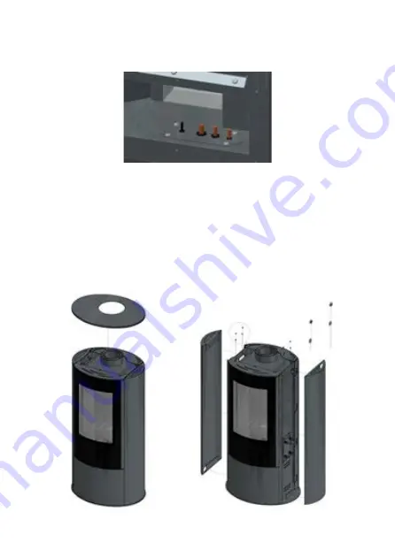
Fig. 8 Méthode de retirer le panneau supérieur et les parois latérales du chauffage Koza AB GAZ

Fig. 7 Méthode de faire passer et sceller le conduit de la capillaire, du conduit de la magnéto, du 

tuyau du brûleur principal et du tuyau du brûleur de contrôle du chauffage KOZA AB GAZ.

En faisant passer les différents conduits à travers le logement du chauffage à gaz, faire attention 

particulière à la façon de leur scellement. Le scellement est réalisé au moyen de coussinets spéciaux 

et de papier résistant à la chaleur. L'installateur devrait sceller les autres éléments avec du silicone 

haute température.

DÉMONTAGE DE L'APPAREIL

Pour pouvoir accéder aux différents éléments du système de contrôle automatique du gaz utilisé dans 

le chauffage Koza AB GAZ, retirez d'abord le couvercle supérieur, puis dévissez les vis de fixation des 

parois latérales. Après avoir dévissé les vis, les parois latérales doivent être soulevées (Fig. 8). Dans 

l'étape suivante, il est nécessaire de démonter le couvercle inférieur. Le couvercle inférieur est fixé avec 

quatre vis M5 (Fig. 9). Pour accéder à la chambre de combustion, au brûleur principal et au module 

de brûleur de contrôle, la porte doit être retirée en dévissant les 8 vis M5 comme indiqué sur la Fig. 

10. Ensuite, retirez la vitre intérieure en dévissant les bandes de pression (16 vis M5). La révision est 

démontée en dévissant 6 vis M5 (Fig. 11).

Summary of Contents for KOZA AB GAZ

Page 1: ...OLNOSTOJ CY OGRZEWACZ POMIESZCZE ZASILANY GAZEM instrukcja obs ugi i monta u kratki GAS FUELED STOVES Installation and operating instructions EN CHAUFFAGE GAZ IND PENDANT Manuel d utilisation et d ins...

Page 2: ...trze one Ani instrukcja ani jakikolwiek materia w niej za warty nie mog by reprodukowane bez pisemnej zgody autora Informacje umieszczone w tym doku mencie mog zosta zmienione bez uprzedzenia Producen...

Page 3: ...zeniem grzewczym zasi lanym gazem palnym Niniejsze urz dzenie posiada oznaczenie CE oraz wykorzystuje wysokiej klasy automatyk do sterowania gazem Kominek spe nia surowe dyrektywy europejskie w odnies...

Page 4: ...4 Rys 1 KOZA AB GAZ zasilana gazem Rys 2 Wymiary gazowego ogrzewacza pomieszcze KOZA AB GAZ...

Page 5: ...przeprowadzi w obecno ci instalatora Przed przyst pieniem do instalacji kominka prosz za pozna si ze wszystkimi elementami dostarczonymi wraz z urz dzeniem W przypadku stwierdzenia jakichkolwiek uszk...

Page 6: ...zczelno urz dzenia UWAGA Urz dzenie w trakcie pracy nagrzewa si i dlatego w trakcie w normalnych warunkach pracy nale y bezwzgl dnie wystrzega si dotykania jakichkolwiek powierzchni urz dzenia wlicza...

Page 7: ...y usytuowany tak by przew d powietrzno spalinowy posiada jak najmniejsz liczb zagi Zagwarantuje to odpowiedni ci g kominowy Wa ne jest tak e aby po pod czeniu ogrzewacza do instalacji gazowej elastycz...

Page 8: ...Zamontowa system zgodnie z obowi zuj cymi przepisami z uwzgl dnieniem wszelkich utrudnie zwi zanych z parciem wiatru na terminal W przypadku ciany atwopalnej zapewni dodatkowy odst p 5 cm pomi dzy ci...

Page 9: ...mu W przypadku wyst pienia skroplin w przewodzie powietrzno spalinowym instalator powinien zastosowa element odwadniaj cy odkraplacz Nale y pami ta o kontroli przewodu powietrzno spalinowego wraz z te...

Page 10: ...nie elektroniki systemu na temperatur powy ej 60 C spowoduje jej nieodwracalne uszkodzenie Maksymalna odleg o pomi dzy uk adem sterowania a palnikiem ogrzewacza jest wyznaczona przez d ugo przewod w c...

Page 11: ...raturowym DEMONTA URZ DZENIA Aby mie mo liwo dost pu do poszczeg lnych element w systemu automatycznego sterowania gazem wykorzystywanego w ogrzewaczu Koza AB GAZ w pierwszej kolejno ci nale y zdemont...

Page 12: ...12 Rys 10 Spos b demonta u drzwi w ogrzewaczu Koza AB GAZ Rys 9 Spos b demonta u drzwi dolnych w ogrzewaczu Koza AB GAZ...

Page 13: ...nie powinno by dostosowane UWAGA Modu palnika g wnego wykorzystywany w ogrzewaczu pomieszcze zasilanym gazem KOZA AB GAZ jest po czony bezpo rednio z wylotem sterownika GV60 UWAGA Wszelkie czynno ci z...

Page 14: ...A TEMPERATURA PRACY Sterownik 0 C to 80 C Odbiornik bez baterii 80 C Odbiornik z bateriami 55 C Pilot 60 C Przew d zap onowy 150 C Kominek zosta przystosowany do pracy z typem gazu i ci nieniem okre l...

Page 15: ...ne uszkodzenie poszczeg lnych podzespo w Przew d doprowadzaj cy gaz do kominka powinien by wyposa ony w zaw r kulkowy o rednicy cala Poszczeg lne elementy instalacji gazowej nie mog by uszczelniane p...

Page 16: ...jest ustawiona na maksimum i nie wymaga r cznej regulacji G owica termopary powinna by w zasi gu p omienia kontrolnego Regulacja ci nienia wylotowego gazu UWAGA 1 Nale y pami ta e jakiekolwiek regula...

Page 17: ...nie wloto we jest w normalnym zakresie wymie sterownik w przeciwnym wypadku podejmij niezb dne kroki w celu zapewnienia w a ciwego ci nienia gazu UWAGA Zablokowanie regulatora ci nienia realizowane je...

Page 18: ...u i tego samego producenta Nie nale y instalowa baterii nowych wraz ze zu ytymi Do zestawu opcjonalnie mo e zosta dokupiony modu zasilaj cy G60 ZB90 Modu ten zasilany jest czterema ba teriami 1 5V typ...

Page 19: ...spos b aby nie przys ania y p omienia kontrolnego oraz otwor w wyloto wych palnika g wnego w przeciwnym razie mo e to powodowa niepoprawn prac kominka Palnik g wny kominka wyposa ony jest w dystanse u...

Page 20: ...OBS UGA Ogrzewacz pomieszcze zasilany gazem KOZA AB GAZ sterowany jest bezprzewodowo z poziomu pilota Standardowo system zasilany jest za pomoc czterech baterii 1 5V instalowanych w odbiorniku Kr tkie...

Page 21: ...zytrzyma przycisk RESET znajduj cy si w obudowie odbiornika a do momentu us yszenia dw ch charaktery stycznych sygna w po czym zwolni przycisk Czynno ci tej powinno si dokona u ywaj c do tego celu cie...

Page 22: ...y zamkn zaw r odcinaj cy dop yw gazu do urz dzenia i skontaktowa si z serwisantem Aktywacja funkcji pilota Zainstaluj baterie Wszystkie dost pne ikony pojawi si na wy wietlaczu i zaczn miga Wci nij pr...

Page 23: ...woduje automatyczne ustawienie zegara wformacie 12 godzin natomiast wyb r C ustawi zegar w formacie 24 godzin Ustawienia czasu 1 Aby mie mo liwo ustawienia dnia tygodnia wci nij jednocze nie przyciski...

Page 24: ...u za pomoc dw ch przycisk w Wci nij jednocze nie przyciski i a do us yszenia dw ch kr tkich sygna w Rozpocz cie sekwencji rozpalania potwierdzi pojawienie si na wy wietlaczu migaj cej ikony palnika Pu...

Page 25: ...uwa nia nale y wcisn i przytrzyma przycisk Tryb czuwania i wy czanie Aby spowodowa prze czenie si urz dzenia w tryb czuwania nale y przy trzyma przycisk a do wygaszenia palnika g wnego Aby wy czy urz...

Page 26: ...m odliczania zniknie Tryby Tryb Termostat Temperatura w pomieszczeniu jest mierzona i por wnywana z temperatur ustawion na termostacie Wysoko p omienia jest automatycznie regulowa na w taki spos b aby...

Page 27: ...na termostacie to wysoko p omienia osi ga swoj maksymaln warto i pozostaje na wysokim poziomie przez d u szy okres czasu Je eli temperatura w pomieszczeniu jest ni sza ni zadana w wczas wysoko p omie...

Page 28: ...ra tur wy czania 3 Ustaw dan temperatur wy czania za pomoc przycisk w lub 4 Aby potwierdzi wci nij Ustawienia dni 5 Na wy wietlaczu zacznie miga symbol ALL Wci nij przycisk lub aby wybra jedn z trzech...

Page 29: ...nale y zresetowa pilota poprzez wyj cie baterii Opcja pomocnicza Opcja ta dost pna jest jedynie w przypadku wk ad w gazowych posiadaj cych wi cej ni jeden palnik W przypadku serii koza AB funkcja poz...

Page 30: ...iank pilota Wymiana baterii w odbiorniku module zasilaj cym Otworzy drzwiczki szafki rozdzielczej Ostro nie wyj odbiornik B6R R8U modu zasilaj cy G60 ZB90 Usun pokryw Usun cztery zu yte baterie typu A...

Page 31: ...rownik z odbiornikiem nie s uszkodzone Sprawd czy elementy systemu sterowania gazem nie s nara one na dzia anie wysokiej temperatury Sprawd czy skrzynka rozdzielcza nie jest nara ona na dzia anie wilg...

Page 32: ...kupu oryginalnego Produktu przez pierwszego u ytkownika ko cowego Produkt mo e sk ada si z wie lu odr bnych cz ci i dla r nych cz ci b d mia y zastosowanie inne okresy gwarancji Producent udziela 2 la...

Page 33: ...em sterownia gazem nie jest uszkodzony Je eli silnik krokowy nie pracuje poprawnie wymie modu stero wania gazem Je eli cewka modu u sterownia gazem nie pracuje poprawnie wymie modu Je eli mikro wy cz...

Page 34: ...ntrolny nie jest zas oni ty elementami dekoracyjnymi Sprawd czy czujnik termopary jest sprawny i poprawnie pod czo ny do modu u sterowania gazem Sprawd czy p omie kontrolny jest w stanie nagrza czujni...

Page 35: ...35 ILUSTRACJE Spos b POPRAWNEGO u o enia polan ozdobnych Rys 19 Poprawne rozmieszczenie element w dekoracyjnych polany Rys 20 Poprawne rozmieszczenie element w dekoracyjnych polany...

Page 36: ...a obci enia minimalnego mbar 5 0 6 5 5 0 6 5 Znamionowe maksymal ne obci enie cieplne wg Hi mbar mbar 5 2 5 2 5 2 Minimalne obci enie cieplne wg Hi mbar 2 7 2 7 2 7 Strumie zu ywanego gazu dla znamion...

Page 37: ...3P 50 I3 30 37 G30 G31 G30 G31 Przystosowany do gazu LPG 37 50 30 37 50 30 37 22 0 24 0 29 7 36 5 regulator zablokowany 5 5 6 0 13 0 15 0 4 5 4 5 4 4 2 3 2 3 2 7 0 14 0 18 0 14 0 17 0 07 0 09 0 09 0 1...

Page 38: ...res smooth and reliable operation of the device by end users This manual contains all of the information necessary for proper installations operation and maintenance of the Freestanding STOVE AB S NOT...

Page 39: ...39 Rys 1 KOZA AB GAZ gas stove Rys 2 Dimensions Freestanding STOVE AB S EN...

Page 40: ...of the fitter Before installing the stove please learn all of the elements that came with the device In the case of any damage or omissions please contact custo mer service The user receives a set in...

Page 41: ...perate the unit As soon as possible shut off the gas ventilate the room where the stove is and contact your service representative Any cracked glass should be immediately replaced In the case of malfu...

Page 42: ...ble wires connect ed to the gas stove were not exposed to excessive bending Stove must be at least 60 mm away from combustible building elements Fig 3 4 The temperature of the walls exposed to direct...

Page 43: ...flue passage through the external wall of the building Install the system in accordance with the applicable regulations including any difficulties related to the wind pressure on the terminal In the...

Page 44: ...internal diameter of 100 mm for the discharge of exhaust gases The concentric line must end with a special cap to allow proper operation of the system The coaxial cable should be terminated with a sp...

Page 45: ...to temperatures exceeding 60 C will result i n irreparable damage Elements of the control system should be installed in a place where the temperature does not exceed 25 C The maximum distance between...

Page 46: ...cone DISASSEMBLY OF THE DEVICE In order to gain access to the individual components of the automatic gas control system used in the AB GAZ heater first remove the top cover and then unscrew the side w...

Page 47: ...47 Figure 10 Removal of the doors Figure 9 Removal of the bottom cover...

Page 48: ...rner with the right one WARNING The main burner module used in gas appliances in the stove consists of two parts connected to the outlet of the GV60 controller by a tee NOTE All activities associated...

Page 49: ...ing a Teflon tape or PTFE tape Please use the sealing elements supplied with the unit If the gas installation needs to be connected to a settler install it according to Fig 12 The settler protects the...

Page 50: ...50 Fig 12 How to install a settler if required...

Page 51: ...he measuring point of the output pressure To do so first remove the metal stove located in the control enclosure 2 Startup the device 3 The pressure regulator is in the upper part of the controller en...

Page 52: ...he adjusting screw Fig 13 The adjustment screw is set so as to provide the maximum flame height 3 Turnthescrewclockwisetoreducetheminimumheightoftheflame 4 Depending on the version of the controller t...

Page 53: ...install new batteries with worn ones The kit can optionally include the G60 ZB90 power module This module is powered by four 1 5V AA batteries and should be connected directly to the receiver in the...

Page 54: ...should be arranged in such a way as not to obscure the flame control and the burner outlet openings otherwise it may cause incorrect operation of the stove The main burner of the stove is equipped wit...

Page 55: ...5V batteries installed in the receiver Short cyclical signals appear for about three seconds when you try to ignite the gas stove and it is necessary to replace the batteries in the receiver A long be...

Page 56: ...have not been properly paired Figure 18 RESET button receiver INFORMATION To view the current version of the software used by the remote control simultaneously press the and Simultaneous pressing the...

Page 57: ...Time Setup 1 To be able to adjust the day of the week press the button and the button 2 Press or to select a number corresponding to the day of the week 1 Monday 2 Tuesday 3 Wednesday 4 Thursday 5 Fri...

Page 58: ...ws the icon Disabling To deactivate the Child Proof function press the and buttons The icon will disappear Manual mode Lighting the fire in the stove with a single button default setting Press the but...

Page 59: ...d until you see the icon The hours box will flash 2 Enter a value using the and buttons 3 To confirm press The minutes box will flash Standby or off mode To make the unit switch to the standby mode ho...

Page 60: ...of the stove at a given temperature Information After the expiry of the countdown time the stove will be extinguished The sleep timer only works in different modes Manual Thermostat and Eco The maximu...

Page 61: ...and ON and OFF Disabling the programmed mode 1 Press the button or the button or the button to go to the manual mode 2 Press the button to go to the Thermostat mode Information Entering the switch on...

Page 62: ...Wednesday 4 Thursday 5 Friday 6 Saturday 7 Sunday Switching on time settings Programme 1 ALL option selected 7 The display shows 1 ON then for a while you will see the ALL symbol Subsequently the hour...

Page 63: ...s the default preset values Entering new settings for switching on and off time for Programmes 1 and 2 will set new values as the default To restore the factory settings for programmes 1 and 2 reset t...

Page 64: ...observing the polarity markings Replace the cover on the back wall of the remote Replacing batteries in the receiver power supply module Open the cabinet door panel Carefully remove the B6R R8U receiv...

Page 65: ...trol burner is not obscured by decorative elements Check if the thermocouple is within the control flame Check whether the combustion chamber requires cleaning Make sure all air inlets to the combusti...

Page 66: ...arranted for a period of 1 year from the date of the purchase of the stove The warranty does not cover insu lating panels heat resistant ceramics The use of the stove the connection method to the chim...

Page 67: ...ly replace the module No spark at the electrode Check the cable connection between the receiver and the electrode Check that the electrode is not damaged Check the operation of the sparker Check that...

Page 68: ...ng the temp sensor The main burner automatically turns off after the stove reaches a certain temperature Check the thermostat setting There is sediment depo sited on the glass Make sure the holes of t...

Page 69: ...69 ILLUSTRATIONS Correct arrangement of decorative logs Fig 19 Correct arrangement of decorative logs Fig 20 Correct arrangement of decorative logs...

Page 70: ...he regulator for minimum load mbar 5 0 6 5 5 0 6 5 Rated thermal load accor ding to Hi mbar 5 2 5 2 5 2 Rated minimum load according to Hi mbar 2 7 2 7 2 7 Consumable gas stream for rated maximum heat...

Page 71: ...0 I3P 37 I3P 50 I3 30 37 G30 G31 G30 G31 LPG 37 50 30 37 50 30 37 22 0 24 0 29 7 36 5 Regulator Blocked 5 5 6 0 13 0 15 0 4 5 4 5 4 4 2 3 2 3 2 7 0 14 0 18 0 14 0 17 0 07 0 09 0 09 0 11 2 2 2 5 5 4 4...

Page 72: ......

Page 73: ...ais d tanch it et l entretien de l appareil ne peuvent tre effectu s que par un installateur technicien qualifi disposant des habilitations appropri es pour une r gion donn e INTRODUCTION Le chauffage...

Page 74: ...74 Fig 1 KOZA AB GAZ gaz Fig 2 Dimensions du chauffage gaz KOZA AB GAZ...

Page 75: ...on doit tre effectu e en pr sence de l installateur Avant d installer le chauffage veuillez v rifier tous les l ments qui sont livr s avec l appareil En cas de dommages ou de d fauts contactez le serv...

Page 76: ...es est cass e enlev e ou non fix e de mani re garantir l tanch it de l appareil ATTENTION Pendant le fonctionnement l appareil chauffe et dans des conditions de travail normales il est im p ratif de n...

Page 77: ...e telle sorte que le conduit de combustion et d air ait le nombre minimum de coudes Cela permettra d assurer un bon tirage de la chemin e Il est gale ment important que lorsque le chauffage est connec...

Page 78: ...ent il faut Installer le syst me en conformit avec les r glementations en vigueur en tenant compte de toutes les difficult s li es la pression du vent sur le terminal En cas de murs inflammables pr vo...

Page 79: ...permettre un fonctionnement correct du syst me En cas de conden sation dans le conduit d air l installateur doit utiliser l l ment de drainage s parateur de gouttes V rifier le conduit d air de gaz d...

Page 80: ...s 60 C entra nera des dommages irr versibles La distance maximale entre le syst me de commande et le br leur du chauffage est d termin e par la longueur des fils reliant le r gulateur de gaz GV60 l le...

Page 81: ...haute temp rature D MONTAGE DE L APPAREIL Pour pouvoir acc der aux diff rents l ments du syst me de contr le automatique du gaz utilis dans le chauffage Koza AB GAZ retirez d abord le couvercle sup r...

Page 82: ...82 Fig 10 M thode de retirer la porte du chauffage Koza AB GAZ Fig 9 M thode de retirer la porte inf rieure du chauffage Koza AB GAZ...

Page 83: ...t ATTENTION Le module de br leur principal utilis dans le chauffage gaz KOZA AB GAZ est directement raccord la sortie du contr leur GV60 ATTENTION Toutes les op rations li es connecter l appareil au g...

Page 84: ...E Allumage pi zo TEMP RATURE DE SERVICE ADMISSIBLE Contr leur 0 C 80 C R cepteur sans piles 80 C R cepteur avec piles 55 C T l commande 60 C C ble d allumage 150 C Le foyer a t adapt pour fonctionner...

Page 85: ...e avec un diam tre de 1 pouce Les diff rents l ments du syst me de gaz ne peuvent pas tre scell s l aide du ruban t flon ou du ruban PTFE utiliser les l ments d tanch it fournis avec l appareil Si l i...

Page 86: ...age de la pression de sortie du gaz ATTENTION 1 Il ne faut pas oublier que les r glages ne doivent tre effectu s que sur un appareil refroidi Raccorder le manom tre au point de mesure de la pression d...

Page 87: ...male remplacer l unit de commande sinon prendre les mesures n cessaires pour assurer une pression de gaz appropri e ATTENTION Le verrouillage du r gulateur de pression est r alis travers le serrage ma...

Page 88: ...es piles du m me type et du m me fabricant Ne pas installer les piles neuves avec les piles us es Il est possible d acheter le module d alimentation G60 ZB90 Ce module est aliment par quatre piles 1 5...

Page 89: ...ts do ivent tre dispos s de mani re ne pas occulter la flamme de contr le et les ouvertures de sortie du br leur principal sinon il peut en r sulter un mauvais fonctionnement du foyer Le br leur princ...

Page 90: ...ouve sur les murs le plancher et le plafond UTILISATION Le chauffage au gaz KOZA AB GAZ est contr l sans fil partir de la t l commande Par d faut le syst me est aliment par quatre piles 1 5 V install...

Page 91: ...ion Pour le faire appuyer et maintenir le bouton RESET situ dans le bo tier du r cepteur jusqu deux bips caract ristiques ensuite rel cher le bouton Cette action doit tre faite au moyen d un l ment mi...

Page 92: ...ne d arr t du gaz et contacter un technicien ACTIVATION DE LA FONCTION DE T L COMMANDE Installer les piles Toutes les ic nes disponibles apparaissent sur l cran et clignotent Appuyer sur le bouton cor...

Page 93: ...automatique de l horloge au format de 12 heures et le choix de C r gle l horloge au format de 24 heures R glage du temps 1 Pour modifier le r glage des jours de la semaine appuyer en m me temps sur l...

Page 94: ...s boutons et jusqu ce que vous enten diez deux bips Le d clenchement de la s quence d allumage est confirm par l ic ne de br leur clignotant Rel cher le bouton L allumage de la flamme de contr le est...

Page 95: ...Pour r duire la hauteur de la flamme ou passer en mode de veille appuyer et maintenir le bouton enfonc Mode de veille et d sactivation Pour passer en mode de veille maintenir le bouton enfonc jusqu te...

Page 96: ...ic ne dispara t avec l indication du temps Minuteur Modes Mode Thermostat La temp rature ambiante est mesur e et compar e la temp rature pr r gl e La hauteur de la flamme est r gl e automatiquement d...

Page 97: ...de la flamme atteint sa valeur maximale et reste un niveau lev pendant une longue p riode de temps Si la temp rature ambiante est inf rieure la temp rature de consigne la hauteur de la flamme est r d...

Page 98: ...cran 3 R gler la temp rature de d sactivation avec les boutons ou 4 Pour valider appuyer sur le bouton R glage des jours 5 Le symbole ALL commence clignoter sur l cran Appuyer sur le ou pour s lection...

Page 99: ...our les program mes 1 et 2 r initialiser la t l commande en retirant les piles Option auxiliaire Cette option est disponible uniquement pour les inserts gaz avec plusieurs br leurs Pour les s ries LEO...

Page 100: ...l arri re de la t l commande Remplacement des piles dans le r cepteur le module d alimentation Ouvrir la porte de l armoire de distribution Retirer doucement le r cepteur B6R R8U le module d alimentat...

Page 101: ...ont pas endommag s S assurer que les l ments du syst me de commande du gaz ne sont pas expos s la chaleur S assurer que la bo te de distribution n est pas expos e l humidit S assurer que les c bles de...

Page 102: ...commence au moment de l achat du produit original par le premier utilisateur final Le produit peut tre consti tu de plusieurs pi ces diff rentes et les diff rentes parties peuvent tre couvertes par de...

Page 103: ...commande du gaz Si la bobine du module de commande du gaz ne fonctionne pas correctement remplacer le module Si le micro interrupteur du module de commande du gaz ne fonc tionne pas correctement rempl...

Page 104: ...contr le n est pas occult e par les l ments d coratifs S assurer que le capteur de thermocouple est fonctionnel et correc tement connect au module de contr le du gaz S assurer que la flamme de contr...

Page 105: ...105 DESSINS M THODE DE POSE CORRECTE DES B CHES D CORATIVES Fig 19 R partition correcte des l ments d coratifs b ches Fig 20 R partition correcte des l ments d coratifs b ches...

Page 106: ...harge minimale mbar 5 0 6 5 5 0 6 5 Charge thermique nominale maximale selon Hi mbar mbar 5 2 5 2 5 2 Charge thermique minimale selon Hi mbar 2 7 2 7 2 7 Flux de gaz consomm pour la charge thermique n...

Page 107: ...I3P 37 I3P 50 I3 30 37 G30 G31 G30 G31 Pour le gaz GPL 37 50 30 37 50 30 37 22 0 24 0 29 7 36 5 r gulateur verrouill 5 5 6 0 13 0 15 0 4 5 4 5 4 4 2 3 2 3 2 7 0 14 0 18 0 14 0 17 0 07 0 09 0 09 0 11 2...

Page 108: ...Kratki pl Marek Bal ul Gombrowicza 4 Wsola 26 660 Jedli sk Poland tel 00 48 48 389 99 00 00 48 48 384 44 88 fax 00 48 48 384 44 88 wew 106 www kratki com PW 11 2017...

Reviews: