Kramer Electronics Ltd.
WP-20CT
– Connecting WP-20CT
9
Connecting to WP-20CT via RS-232
You can connect to
WP-20CT
via an RS-232 connection
using, for example, a PC.
WP-20CT
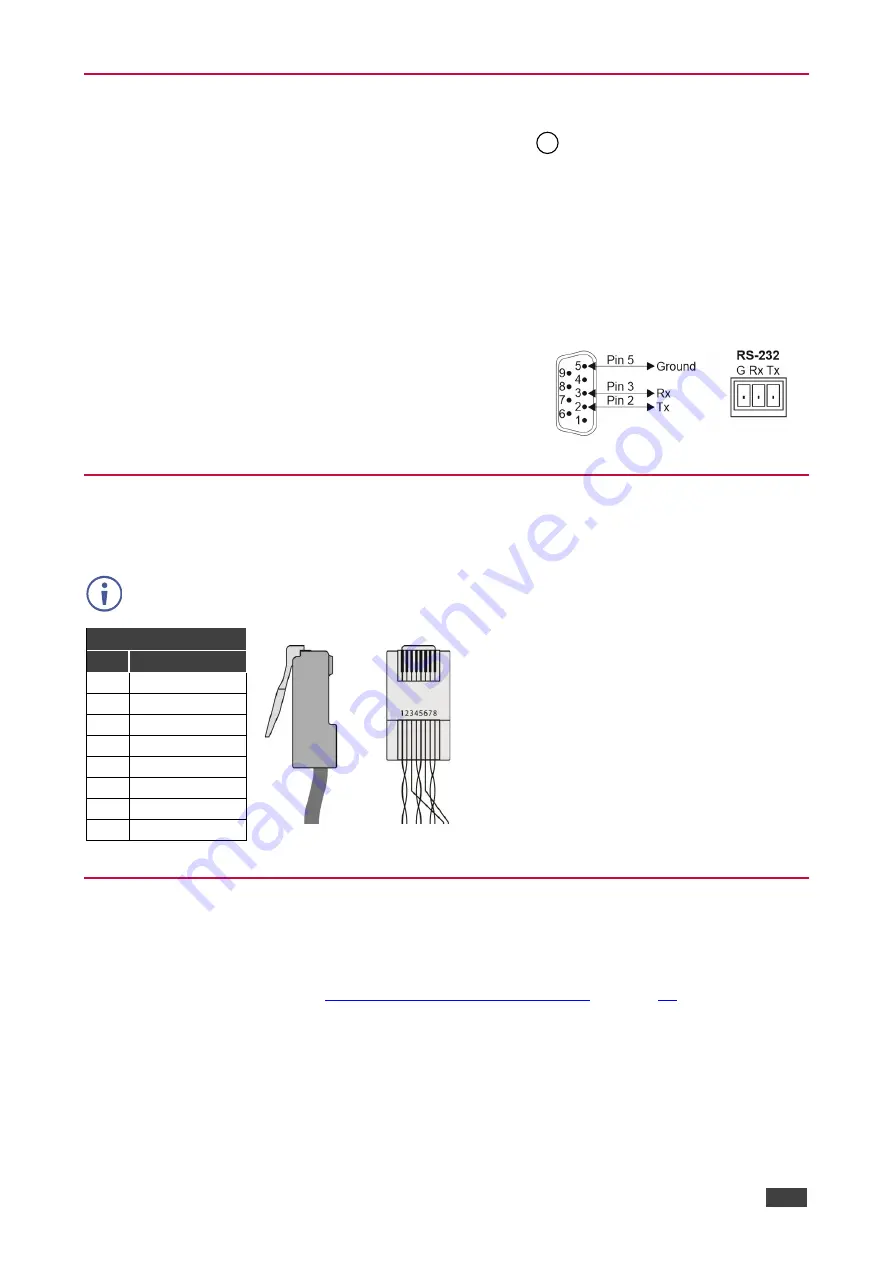
features an RS-232 3-pin terminal block connector allowing the RS-232 to control
WP-20CT
.
Connect the RS-232 terminal block on the rear panel of
WP-20CT
to
a PC/controller, as
follows:
From the RS-232 9-pin D-sub serial port connect:
•
Pin 2 to the TX pin on the
WP-20CT
RS-232 terminal block
•
Pin 3 to the RX pin on the
WP-20CT
RS-232 terminal block
•
Pin 5 to the G pin on the
WP-20CT
RS-232 terminal block
RS-232 Device
WP-20CT
Wiring RJ-45 Connectors
This section defines the HDBT pinout, using a straight pin-to-pin cable with RJ-45 connectors.
For HDBaseT cables, it is recommended that the cable ground shielding be
connected/soldered to the connector shield.
EIA /TIA 568B
PIN Wire Color
1
Orange / White
2
Orange
3
Green / White
4
Blue
5
Blue / White
6
Green
7
Brown / White
8
Brown
Connecting USB-C Port Directly to PC
You can connect the USB-C IN port of
WP-20CT
directly to the USB port on your PC using a
USB-C to USB-C cable. This enables you to configure and operate the device using the
embedded web pages (see
Operating and Controlling WP-20CT
After connecting
WP-20CT
to the USB-C port, configure your PC as follows:
1. Click
Start
>
Control Panel
>
Network and Sharing Center
.
2. Click
Change Adapter Settings
.
3. Highlight the
ASIX
network adapter to connect to the device and click
Change settings
of this connection
.
13


