background image

Communication Protocol 2000 


29 

11  Communication Protocol 2000

1


The 

VS-88HCB 

is compatible with Kramer’s Protocol 2000. Communication 

with the 

VS-88HCB 

uses four bytes of information as defined below. Data is 

transferred at 9600 baud with no parity, 8 data bits and 1 stop bit. 

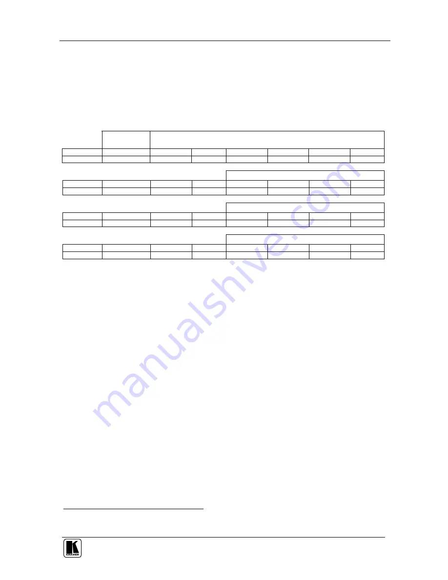
Table 7: Protocol Definitions 

MSB 


LSB 


DESTIN 

ATION 

INSTRUCTION 

N5 

N4 

N3 

N2 

N1 

N0 

1st byte 


INPUT 

I3 


2nd byte 


OUTPUT 

O3 


3rd byte 


MACHINE NUMBER  

M2 

M1 


4th byte 


1

st

 BYTE:  Bit 7 – Defined as "0",    


D – “DESTINATION BIT” 

This bit is always "low", when sending from the PC to the Matrix Switchers, and "high" for information sent to the PC. 

N5…N0 – “INSTRUCTION”. 

The function that is to be performed by the Matrix Switcher (s) is defined by these 6 bits. Similarly, if a function is performed 

via the machine’s keyboard, then these bits are set with the 

INSTRUCTION #

 which was performed. The instruction codes 

are defined according to the table below (

INSTRUCTION #

 is the value to be set for N5…N0). 


2

nd

 BYTE:   

Bit 7 – Defined as "1". 


Bits 4 – 6 - Defined as "0". 


I3… I0 – “INPUT”. 

When  switching  via  RS-232  for  RS-  485  (for  instruction  codes  1  and  2),  these  bits  set  the  input  that  is  to  be  switched. 

Similarly, if switching is done via the machine’s keyboard, then these bits are set with the input number which was switched. 

For disconnect, set as 0. For other operations, these bits are defined according to the table. 


3

rd

 BYTE:   

Bit 7 - Defined as "1". 

                    Bits 4-6 Defined as "0". 

                    O3 – O0 – “OUTPUT”. 

When switching via RS-232 or RS-485 (for instruction codes 1 and 2), the output to switch is set by these bits. Similarly, if 

switching is done via the machine’s keyboard, then these bits are set with the output number that was switched. For other 

operations, these bits are defined according to the table. 


4th BYTE:


Bit 7 – Defined as "1".  

Bits 3-6 Defined as "0".   


M2… M0 – “Machine Number”. 


Machine Number = (DIP – Switch Code) + 1. 


1 You can download our user-friendly “ Software for Calculating Hex Codes for Protocol 2000”  from the technical support 
section on our Web site at: http://www.kramerelectronics.com 

im Vertrieb von            CAMBOARD Electronics

www.camboard.de

Tel. 07131 911201
Fax 07131 911203

[email protected]

Summary of Contents for VS-88HCB

Page 1: ...Kramer Electronics Ltd USER MANUAL Model VS 88HCB 8x8 Component Video Audio Matrix Switcher im Vertrieb von CAMBOARD Electronics www camboard de Tel 07131 911201 Fax 07131 911203 ce info camboard de...

Page 2: ...Unit Characteristics 19 7 2 Selecting and Connecting an Output and or Input 19 7 3 Choosing the Audio Follow Video or Breakaway Option 20 7 3 1 Setting the Audio Follow Video Option 20 7 3 2 Setting...

Page 3: ...for example using an RC 3000 14 Figure 9 Local Area Connection Properties Window 15 Figure 10 Internet Protocol TCP IP Properties Window 16 Figure 11 VS 88HCB Dipswitches 17 Figure 12 Control Configur...

Page 4: ...e2 and this user manual3 2 Getting Started We recommend that you Unpack the equipment carefully and save the original box and packaging materials for possible future shipment Review the contents of th...

Page 5: ...KRAMER SIMPLE CREATIVE TECHNOLOGY Getting Started 2 im Vertrieb von CAMBOARD Electronics www camboard de Tel 07131 911201 Fax 07131 911203 ce info camboard de...

Page 6: ...nd YUV simultaneously Includes an ETHERNET connection that supports easy dial up and Internet system remote control requiring only a dedicated IP address1 and a modem in the remote location whether it...

Page 7: ...CREATIVE TECHNOLOGY Your VS 88HCB 4 Figure 1 VS 88HCB 8x8 Component Video Audio Matrix Switcher Front Panel im Vertrieb von CAMBOARD Electronics www camboard de Tel 07131 911201 Fax 07131 911203 ce in...

Page 8: ...Button Press the RCL button followed by an INPUT button2 to recall a setup from the non volatile memory 8 STO Button Press the STO button followed by an INPUT button2 to store the current settings 9...

Page 9: ...CREATIVE TECHNOLOGY Your VS 88HCB 6 Figure 2 VS 88HCB 8x8 Component Video Audio Matrix Switcher Rear Panel im Vertrieb von CAMBOARD Electronics www camboard de Tel 07131 911201 Fax 07131 911203 ce inf...

Page 10: ...machine number 4 is for RS 485 bus termination 5 is for Reply 8 is for RS 485 PC communication 22 RS 232 9 pin D sub Port Connect to the PC or the remote controller 23 Video Y S PDIF C Connect to the...

Page 11: ...o 60 meters when used with three extension cables2 Connect the external IR receiver to the REMOTE IR 3 5mm connector Control the VS 88HCB using the front panel buttons or remotely via the Kramer RC IR...

Page 12: ...fuse replacement see the value printed on the product label 5 The machine is earthed grounded in a reliable way and is connected only to an electricity socket with grounding Pay particular attention...

Page 13: ...C OUT 3 BNC connectors to an s Video acceptor for example an s Video display Y CB PB and CR PR OUT 5 BNC connectors to a component video acceptor for example a projector 4 Connect the corresponding ba...

Page 14: ...hannels for the same format For example if the Video Y Channel is used for composite video then the output channel Video Y 1 should be used similarly Figure 3 Connecting the VS 88HCB 8x8 Component Vid...

Page 15: ...s how to wire a balanced input output connection L R G G Figure 4 Connecting the Balanced Stereo Audio Input Output Figure 5 illustrates how to wire an unbalanced acceptor to the balanced output of th...

Page 16: ...your PC to the RS 232 9 pin D sub rear panel port on the VS 88HCB unit as Figure 7 illustrates2 9 pin D sub From PC 9 pin D sub Male If a shielded cable is used connect the shield to PIN 5 PIN 4 is c...

Page 17: ...485 rear panel port of the RC 3000 to the B PIN on the RS 485 rear panel port of the VS 88HCB unit If shielded twisted pair cable is used the shield may be connected to the G Ground PIN on one of the...

Page 18: ...ssover cable with RJ 45 connectors This type of connection is recommended for identification of the factory default IP Address of the VS 88HCB during the initial configuration After connecting the Eth...

Page 19: ...HCB to the Ethernet port on a network hub or network router via a straight through cable with RJ 45 connectors 6 4 3 Configuring the Ethernet Port After connecting the Ethernet port you have to instal...

Page 20: ...ne in the input expansion configuration in the factory default these DIPs are set to ON 4 RS 485 TERM ON for RS 485 Line Termination factory default OFF for no RS 485 Line Termination 5 Reply ON enabl...

Page 21: ...CHINE Dipswitch Settings DIPS MACHINE 1 2 3 1 Master ON ON ON 2 OFF ON ON 3 ON OFF ON 4 OFF OFF ON 5 ON ON OFF 6 OFF ON OFF 7 ON OFF OFF 8 OFF OFF OFF 6 5 2 Setting the Reply Dipswitch Dipswitch 5 the...

Page 22: ...lecting and Connecting an Output and or Input To switch an input to an output press the desired OUTPUT button followed by the desired INPUT button In addition to Disconnect a video audio Input from a...

Page 23: ...3 2 Setting the Breakaway Option To set the Breakaway option Press either the AUDIO for audio control only or the VIDEO for video control only button If the AUDIO button illuminates switching operati...

Page 24: ...he Confirm mode do the following 1 Press an OUTPUT INPUT combination The corresponding input number that is displayed in the STATUS 7 segment Display blinks The TAKE button also blinks 2 Press the bli...

Page 25: ...links 2 Press the appropriate INPUT SELECTOR button the INPUT SELECTOR button corresponding to the setup The memory recalls the stored data from that reference 7 5 3 Deleting an Input Output Configura...

Page 26: ...s and acceptors and the power cord to each VS 88HCB unit 2 On each VS 88HCB set the SELF ADDRESS as required1 3 Connect the RS 232 port on the first VS 88HCB unit to the PC using the Null modem adapte...

Page 27: ...EATIVE TECHNOLOGY Controlling Several VS 88HCB Units 24 Figure 12 Control Configuration via RS 232 and RS 485 im Vertrieb von CAMBOARD Electronics www camboard de Tel 07131 911201 Fax 07131 911203 ce...

Page 28: ...both the RC 30002 and on the last VS 88HCB unit set DIP 4 to ON 4 Connect the RS 485 ports on the RC 3000 to the RS 485 ports on each of the VS 88HCB units as follows Connect the A PIN on the RS 485 r...

Page 29: ...on via the ETHERNET Port To control several units via the ETHERNET connect the Master unit SELF ADDRESS 1 via the ETHERNET port to the LAN port of your PC Using your PC initially configure the setting...

Page 30: ...detachable terminal blocks MAX OUTPUT LEVEL VIDEO 2 8Vpp AUDIO 24Vpp BANDWIDTH 3dB VIDEO 300MHz Fully Loaded AUDIO 100kHz S N RATIO VIDEO 74dB AUDIO 84dB unweighted 1Vpp CROSSTALK all hostile VIDEO 50...

Page 31: ...CB Table 6 shows the HEX codes for switching the master VS 88HCB Table 6 Hex Codes for Switching the Master VS 88HCB 8 7 6 5 4 3 2 1 OUT IN 1 IN 2 IN 3 8 7 6 5 IN 4 IN 5 IN 6 7 7 7 7 7 7 7 7 IN 7 8 8...

Page 32: ...ION is the value to be set for N5 N0 2nd BYTE Bit 7 Defined as 1 Bits 4 6 Defined as 0 I3 I0 INPUT When switching via RS 232 for RS 485 for instruction codes 1 and 2 these bits set the input that is t...

Page 33: ...19 STORE STATUS Set as SETUP 1 8 0 to store parameters 1 to delete setup 2 7 9 20 RECALL STATUS Set as SETUP 1 8 Don t care 2 7 10 21 to 56 NOT USED 57 SET AUTO SAVE for auto save 0 no save Don t car...

Page 34: ...1 to SETU P 8 are the settings saved in the switcher s memory i e those used for Store and Recall NOTE 8 Under normal conditions the machine s present status is saved each time a change is made The po...

Page 35: ...ailure to followinstructions supplied with the product iii Repairorattemptedrepairby anyonenot authorized byKramer iv Anyshipment oftheproduct claims must bepresentedtothe carrier v Removalorinstallat...

Page 36: ...f Kramer distributors visit our Web site www kramerelectronics com where updates to this user manual may be found We welcome your questions comments and feedback Caution Safety Warning Disconnect the...

Reviews: