background image


VS-21DPIR - Connecting the VS-21DPIR 


Connecting the VS-21DPIR  


Always switch off the power to each device before connecting it to your 

VS-21DPIR

. After connecting your 

VS-21DPIR

, connect its power and 

then switch on the power to each device. 

To connect the 

VS-21DPIR

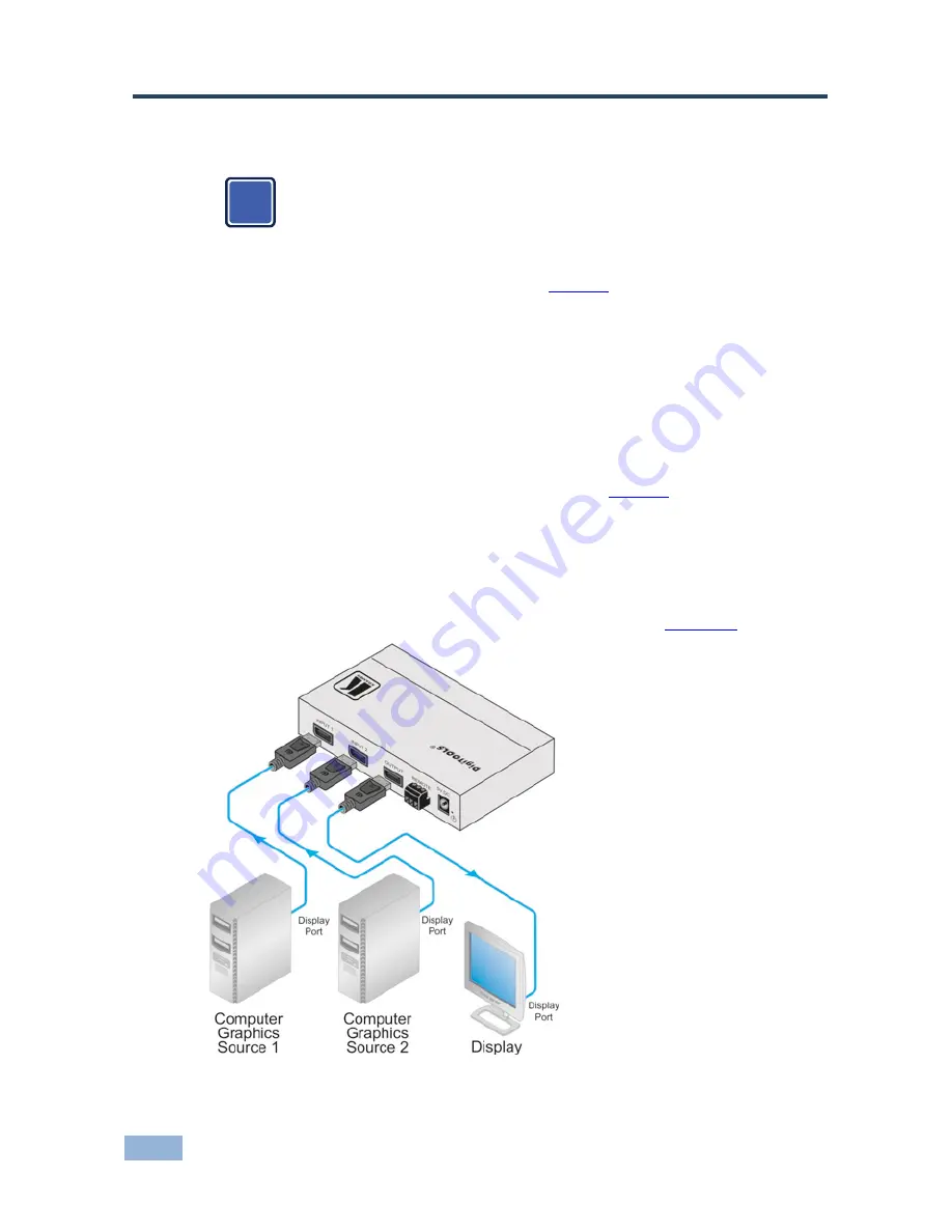
, as the example in 

Figure 2

 shows, do the following: 

1.  Connect up to two computer graphics sources to INPUT 1 and INPUT 2. 

2.  Connect the OUTPUT connector to the DisplayPort acceptor (for example, a 

display), using the Kramer DisplayPort cable. 

You can connect the DP output to an HDMI acceptor by using an appropriate adapter 
and setting the DIP-switches. 

3.  Connect the 5V DC power adapter to the power socket and connect the 

adapter to the mains electricity (not illustrated in 

Figure 2

). 

4.  Press the SELECT button to choose which DP input to route to the output. 

The SELECT button toggles between INPUT 1


and INPUT 2, lighting the  

IN 1 LED when INPUT 1 is selected, or the IN 2


LED when IN 2 is selected. 

Alternatively you can press key 1 or 2 on the remote transmitter, once setup (see 
section  4.1), or use the contact closure remote control pins (see 

Section  4.1

). 


Figure 2: Connecting the VS-21DPIR


2x1 DisplayPort Switcher 

i

Summary of Contents for VS-21DPIR

Page 1: ...KRAMER ELECTRONICS LTD USER MANUAL MODEL VS 21DPIR 2x1 DisplayPort Switcher P N 2900 300265 Rev 3...

Page 2: ......

Page 3: ...Defining the VS 21DPIR 2x1 DisplayPort Switcher 4 4 Connecting the VS 21DPIR 6 4 1 Using the Remote Control Transmitter 7 4 2 Controlling via the REMOTE Terminal Block Connector 7 5 Technical Specific...

Page 4: ...ow appear in 11 groups that are clearly defined by function GROUP 1 Distribution Amplifiers GROUP 2 Switchers and Routers GROUP 3 Control Systems GROUP 4 Format Standards Converters GROUP 5 Range Exte...

Page 5: ...ormance Use only good quality connection cables we recommend Kramer high performance high resolution cables to avoid interference deterioration in signal quality due to poor matching and elevated nois...

Page 6: ...WEEE Directive 2002 96 EC aims to reduce the amount of WEEE sent for disposal to landfill or incineration by requiring it to be collected and recycled To comply with the WEEE Directive Kramer Electro...

Page 7: ...e Features a maximum resolution of 2560x1600 pixels and a total maximum data rate of 10 8Gbps over four lanes Is HDCP compliant and HDTV compatible Passes the EDID signals from the display device to t...

Page 8: ...tact closure switch see section 4 1 5 5V DC 5V DC connector for powering the unit 6 REMOTE IR Receiver Window Receives signals from the infrared remote control transmitter 7 REMOTE IR LED The red LED...

Page 9: ...playPort cable You can connect the DP output to an HDMI acceptor by using an appropriate adapter and setting the DIP switches 3 Connect the 5V DC power adapter to the power socket and connect the adap...

Page 10: ...ure 1 and press the GROUP key 2 Press key 11 This sets and saves the group number To switch INPUT 1 or 2 to the output via the remote control transmitter press key 1 or 2 4 2 Controlling via the REMOT...

Page 11: ...control contact closure remote control pins INDICATOR LEDs IN 1 IN 2 OUT and ON LEDs POWER SOURCE 5V DC 70mA OPERATING TEMPERATURE 0 to 40 C 32 to 104 F STORAGE TEMPERATURE 40 to 70 C 40 to 158 F HUMI...

Page 12: ......

Page 13: ...sit our Web site where updates to this user manual may be found We welcome your questions comments and feedback Web site www kramerelectronics com E mail info kramerel com P N 2900 300265 Rev 3 SAFETY...

Reviews: