background image

Technical Specifications 


15 

8.2  Making the Transition 

You can make the transition in two ways: 


Manually, for each separate transition using the T-bar control lever

1


Automatically, via the TAKE button, which implements the transition at 

the pace set by the SPEED

2


knob 

8.2.1 

Making a Transition Manually 

To make the transition, manually: 


Slide the T-bar handle upwards

3

 or downwards

4


8.2.2 

Making a Transition Automatically 

To make the transition, automatically: 


Rotate the SPEED knob

2

 to the right (increasing the transition speed) or 

to the left (decreasing the transition speed). When the knob is turned to the 

extreme counter-clockwise position (off), the switch will be engaged to turn 

the knob off. In this position, the speed setting is controlled via the setting in 

the 

VP-727

 OSD menu 


Pressing the 

TAKE

 button

5

 causes the transition to occur automatically 

9  Technical Specifications 

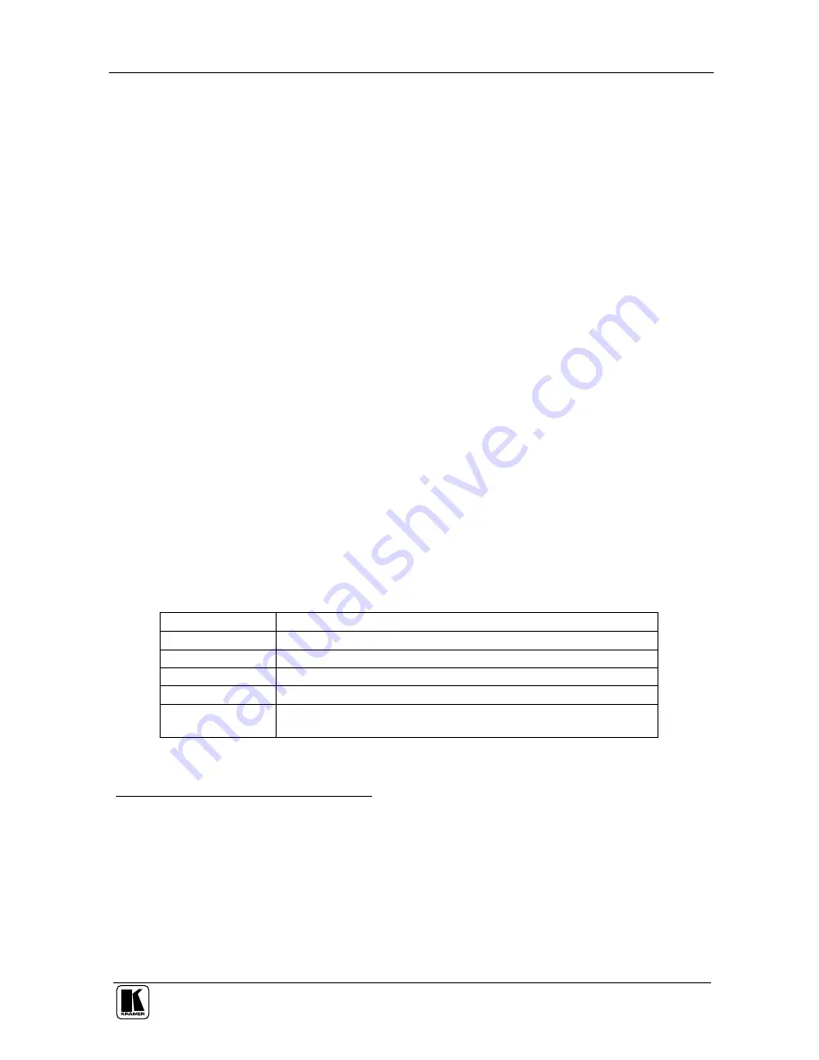
Table 4 includes the technical specifications: 

Table 4: Technical Specifications

6

 of the VP-727T 

PORTS: 

4 sets of RS-485 3-PIN Terminal Block Ports 

CONTROLS: 

Front panel buttons, RS-232, and RS-485 

POWER SOURCE:  12 VDC, 240mA 
DIMENSIONS: 

19” (W), 3.4” (D), 4RU (H) rack mountable

7


WEIGHT: 

1.58kg. (3.5 lbs.) approx. 

ACCESSORIES: 

Gooseneck lamp, null-modem adapter, power supply, rack ears 

kit

8

, and table-top brackets  


1 Item 23 in Figure 1 and Table 1 
2 Item 19 in Figure 1 and Table 1 
3 The PREVIEW LED lights (item 21 in Figure 1 and Table 1) 
4 The PREVIEW LED lights (item 22 in Figure 1 and Table 1) 
5 Item 20 in Figure 1 and Table 1 
6 Specifications are subject to change without notice 
7 48.2cm (W), 8.6cm (D), 17.7cm (H) 
8 A pair of rack ears, two spacers and ten screws 

Summary of Contents for VP-727T

Page 1: ...Kramer Electronics Ltd USER MANUAL Model VP 727T Presentation Switcher Control Panel...

Page 2: ...omatically 15 9 Technical Specifications 15 Figures Figure 1 VP 727T Presentation Switcher Control Panel 4 Figure 2 VP 727T Presentation Switcher Control Panel Side Panel 6 Figure 3 Cut Out Dimensions...

Page 3: ...igher to work with the VP 727T The package includes the VP 727T gooseneck lamp null modem adapter power supply rack ears kit3 table top brackets and this user manual4 2 Getting Started We recommend th...

Page 4: ...panel dedicated specifically to control the VP 727 It is ergonomically and aesthetically designed in a rugged professional 19 4U rack mountable metal enclosure with the button layout in the style of t...

Page 5: ...your switcher is rack mounted near to the source devices you can conveniently place the VP 727T on a table or desk away from the equipment rack Has a gooseneck lamp included that can be plugged into t...

Page 6: ...KRAMER SIMPLE CREATIVE TECHNOLOGY Your VP 727T Presentation Switcher Control Panel 4 Figure 1 VP 727T Presentation Switcher Control Panel...

Page 7: ...down see section 8 2 19 SPEED Knob Adjusts the TAKE button transition speed 20 TAKE Button5 Pressing TAKE causes the transition to occur automatically 21 PREVIEW LED Lights when the T bar Controller...

Page 8: ...3 MACH 4 Connects to the RS 485 port1 on the VP 727 which is recognized as machine 4 4 MACH 3 Connects to the RS 485 port1 on the VP 727 which is recognized as machine 3 5 MACH 2 Connects to the RS 4...

Page 9: ...t the location where you want to insert the VP 727T Figure 3 illustrates the cut out template not to scale defining the surface that you have to cut out to install your VP 727T Figure 3 Cut Out Dimens...

Page 10: ...rough the Bracket Slits 4 Be sure that the upper outer rim is situated parallel to the edge of the desktop 5 Screw the mounting butterfly screws until they reach the desktop surface from the underneat...

Page 11: ...ine in the rack before you attach any cables or connect the machine to the power If you are using a Kramer rack adapter kit for a machine that is not 19 see the Rack Adapters user manual for installat...

Page 12: ...machine 3 MACH 4 to the RS 485 port of the VP 727 which will be recognized as machine 4 2 Connect the 12V DC power adapter to the power socket and connect the adapter to the mains electricity not ill...

Page 13: ...Connecting the VP 727T 11 Figure 7 Connecting the VP 727T...

Page 14: ...terminal block ports of the VP 727T to the respective VP 727 machine connect the A PIN of the VP 727T to the A PIN of the VP 727 B PIN of the VP 727T to the B PIN of the VP 727 If shielded twisted pai...

Page 15: ...adapter Connect the RS 232 DB9 port on your PC to the RS 232 DB9 rear panel port on the VP 727T unit forming a cross connection1 as Figure 9 illustrates DB9 ToPresentation Switcher Scaler DB9 FromPC...

Page 16: ...on 8 2 8 1 Using the VP 727T WIPE DIRECTION Buttons To set the wipe direction use the WIPE DIRECTION buttons2 see Table 3 Table 3 Defining the WIPE DIRECTIONS Buttons EFFECTS WIPE DIRECTIONS Wipe Choi...

Page 17: ...he speed setting is controlled via the setting in the VP 727 OSD menu Pressing the TAKE button5 causes the transition to occur automatically 9 Technical Specifications Table 4 includes the technical s...

Page 18: ...ct fire water lightning orother acts of nature ii Product modification or failure tofollowinstructions suppliedwith theproduct iii Repairorattemptedrepairby anyonenot authorized byKramer iv Anyshipmen...

Page 19: ...or the latest information on our products and a list of Kramer distributors visit our Web site www kramerelectronics com where updates to this user manual may be found We welcome your questions commen...

Reviews: