


KRAMER ELECTRONICS, LTD.
6
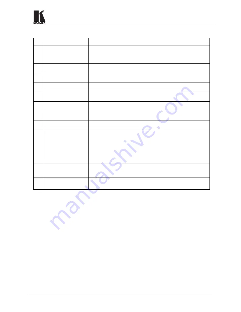
Table 2: VP-88 Rear Panel Features
No.
Feature
Function
1.
H & V
Channels
termination switches
These switches, when released, allow the upper input channels to be used for
TTL level H & V sync signals (RGBHV operation). When pressed - the input
channels become analog video channels, the same as the lower RGB channels,
and the machine can be used for 5 identical video channels.
2.
1-8 AUDIO INPUTS
terminal blocks
Audio inputs used to connect the balanced stereo audio input sources.
3.
1-8 AUDIO OUTPUTS
terminal blocks
Audio outputs used to connect the balanced stereo audio output acceptors.
4.
RS-485
terminal block
Used for bi-directional communication with another Matrix Switcher or PC
through the RS-485 interface.
5.
EXT. SYNC
BNC
connector
Used to connect an external video sync input. The external sync input is
selected by the
SYNC Select
switch.
6.
SYNC Select
switch
Selects either an external sync, from the external source, or internal sync,
which is normally inputted via the
VIDEO INPUT #1
connector.
7.
VIDEO INPUTS
BNC
connectors
Video inputs used to connect the video sources.
8.
VIDEO OUTPUTS
BNC
connectors
Video outputs used to connect the video acceptors.
9.
DB-9 female
RS-232
connector
Used to control the Matrix Switcher (see section 9.4 for more details
concerning RS-232 operation) from a PC, or remote control device, through an
RS-232 interface and a null-modem adapter (provided with the machine).
NOTE
Operation of the machine from a remote PC
may be done using the
K-Switch
control
Software (provided with the machine).
10.
Setup
DIP switches
Allow proper configuration of the control signals received and transmitted
through the RS-232 (or RS-485) control port, master/slave modifications, line
termination and device ID numbers.
11.
Power Connector
A 3-prong AC connector allows power to be supplied to the unit. Directly
underneath this connector, a fuse holder houses the appropriate fuse.
6
INSTALLATION
6.1 Rack
Mounting
The
VP-88
may be rackmounted in a standard 19” (3U) EIA rack assembly and includes rack “ears” at the ends
of the front panel. This device does not require spacing above or below the unit for ventilation. To rack mount
the
VP-88
, simply place the unit’s rack ears against the rails of the rack, and insert standard screws through each
of the four corner holes in the rack ears.
7
CONNECTING TO VIDEO DEVICES
Video / RGBHV sources and output devices may be connected to the
VP-88
through the BNC type connectors
located on the back of the unit. When using the matrix for RGBHV signals, all signal connections that use more
than one cable interconnecting between devices should be of equal length. (Example: cables between a PC and
the machine should be equal in length).
8
CONNECTING TO AUDIO DEVICES
Audio sources and output devices (such as amplifiers or recorders) are connected to the machines through the
terminal block connectors located at the back of the machines.


