background image

Kramer Electronics Ltd. 


VP-554X 

– Operating and Controlling VP-554X 

28 


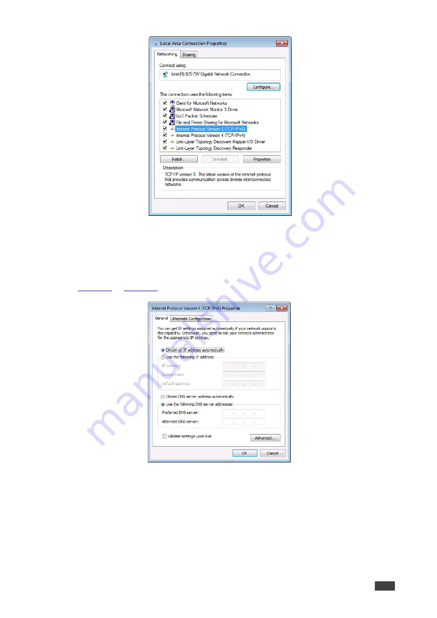
Figure 9: Local Area Connection Properties Window 

4.  Highlight either 

Internet Protocol Version 6 (TCP/IPv6)

 or 

Internet Protocol Version 4 

(TCP/IPv4)

 depending on the requirements of your IT system. 

5.  Click 

Properties

The Internet Protocol Properties window relevant to your IT system appears as shown in 

Figure 10

 or 

Figure 11

. 


Figure 10: Internet Protocol Version 4 Properties Window 

Summary of Contents for VP-554X

Page 1: ...P N 2900 301360 Rev 1 www kramerAV com USER MANUAL MODEL VP 554X Presentation Switcher Scaler...

Page 2: ...Front Panel 12 Resetting the Resolution 13 Locking the Front Panel 13 Controlling Device Operation Via the OSD Menu 13 Operating via Ethernet 27 Using Embedded Web pages 30 Browsing Web Pages 30 Switc...

Page 3: ...nal quality due to poor matching and elevated noise levels often associated with low quality cables Do not secure the cables in tight bundles or roll the slack into tight coils Avoid interference from...

Page 4: ...dded and balanced analog stereo audio up to 2 microphone inputs DSP audio features and a built in stereo power amplifier It includes a built in Ethernet switch and supports legacy RS 232 and IR Ethern...

Page 5: ...after switching the power off and then on again Advanced and User friendly Operation Multiple aspect ratio selections STO and RCL buttons a RESET TO XGA 1080P button to hardware reset the output reso...

Page 6: ...staging Any application where high quality conversion and switching of multiple and different video signals to graphical data signals is required for display or projection purposes Controlling your V...

Page 7: ...old until button flashes once to recall the stored configuration OSD OUT LEDs Indicates on which output the OSD is currently displayed OUT 1 to OUT 4 OSD SELECT Button Press to select the output on wh...

Page 8: ...C IN 15 pin HD Connector Connect to a VGA computer graphics source VIDEO INPUT Connectors HDBT IN1 to HDBT IN4 HDBT IN RJ 45 Connector Connect to an HDBT transmitter IN 1 to IN 4 When connecting a dev...

Page 9: ...te the audio signals Enables easy integration of the audio system with PA systems usually used for alarms or other public audio messages MIC 3 pin Terminal block Connectors Connect to microphones Mic...

Page 10: ...Caution Mount VP 554X before connecting any cables or power Warning Ensure that the environment e g maximum ambient temperature air flow is compatible for the device Avoid uneven mechanical loading A...

Page 11: ...HDMI adapter When using this adapter you can connect the audio signal via the terminal block connector 2 Connect a VGA source to the PC IN 15 pin HD connector 3 Connect an HDBT IN transmitter for exam...

Page 12: ...controlled device to control it via commands sent from the VP 554X RS 232 CONTROL 3 pin terminal block connector port to a PC to control the unit 9 Connect the MUTE 2 pin terminal block contact closu...

Page 13: ...ock connector allowing the RS 232 to control VP 554X Connect the RS 232 terminal block on the rear panel of VP 554X to a PC controller as follows From the RS 232 9 pin D sub serial port connect Pin 2...

Page 14: ...net on page 27 Routing an input to an output To route an input to an output via the front panel 1 Press an OUT button 1 to 4 2 Press an HDMI input 1 to 6 an HDBT input 1 to 4 or a PC IN button Routing...

Page 15: ...Panel To unlock lock the front panel buttons Press and hold for about 3 seconds to lock unlock the front panel buttons Controlling Device Operation Via the OSD Menu VP 554X enables controlling and def...

Page 16: ...on page 16 Setting Screen Freeze on page 16 Setting Screen Blank State on page 17 Adjusting PC Image Parameters on page 17 Adjusting the Image on page 17 Setting Audio Parameters on page 18 Setting Au...

Page 17: ...elected Selecting the Image Size Set the image size on the selected OSD output To set the image size 1 On the front panel press MENU The menu appears 2 Select VIDEO then select SIZE 3 Press ENTER and...

Page 18: ...z 2048x1080 60Hz 1920x1080P 50Hz 3840x2160P 50Hz 1440x900 60Hz 2560x1440 60Hz RB 1920x1080P 24Hz 3840x2160P 60Hz 3 Press ENTER Output parameters are defined To recover if the unit outputs at a resolut...

Page 19: ...ct PC SETUP Menu Item Function AUTO SETUP auto adjusts the image centers it correctly on the screen every time the input is switched to VGA or when the input resolution changes PC setup messages appea...

Page 20: ...default EMBEDDED HDMI 1 to 6 Select EMBEDDED ANALOG or AUTOMATIC default EMBEDDED selects the embedded HDMI audio source ANALOG selects the analog audio corresponding to the input and AUTOMATIC defau...

Page 21: ...s to lessen the talkover output audio decrease level Trigger dB Set the trigger value to determine the microphone threshold level that triggers the audio output level decrease Attack Time Set the atta...

Page 22: ...feature to limit the maximum speaker volume level 0 100 Default 80 LINE HARDSTOP Set the monitor hard stop Use this feature to limit the maximum volume level on the line output 0 100 Default 80 SPEAK...

Page 23: ...s ENTER The input volume is adjusted Defining Microphone Settings Define the following microphone settings The MIC SETTING menu appears in the OSD output 1 menu only To define microphone settings 1 On...

Page 24: ...to set USB 3 to follow HDMI 3 select HDMI 3 and set to USB 3 5 Press ENTER For each parameter USB settings are defined Setting OSD Parameters VP 554X enables adjusting the position timing and display...

Page 25: ...fault or OFF Note that 1 HDCP must be enabled ON to support HDCP encrypted sources 2 Sources such as Mac computers always encrypt their outputs when detecting that the sink supports HDCP If the conten...

Page 26: ...that input To set the switching mode 1 On the front panel press MENU The menu appears 2 Click ADVANCED and select AUTO SWITCH 3 Click ENTER and select AUTO SCAN LAST CONNECTED or OFF 4 Press ENTER Sw...

Page 27: ...OUTPUT HDBT1 OUTPUT HDMI2 OUTPUT HDBT2 OUTPUT HDMI3 OUTPUT HDBT3 OUTPUT HDMI4 OUTPUT HDBT4 USER EDID Def 1080P 2CH Def 1080P MCH Def 4K3G 2CH PC EDID Default EDID or USER EDID The selected EDID file i...

Page 28: ...Device information includes the selected source the input and output resolutions the HDCP status and the software version To view the information 1 On the front panel press MENU The menu appears 2 Cli...

Page 29: ...7 Via a network hub switch or router using a straight through cable see Connecting Ethernet Port via a Network Hub on page 29 Note If you want to connect via a router and your IT system is based on IP...

Page 30: ...light either Internet Protocol Version 6 TCP IPv6 or Internet Protocol Version 4 TCP IPv4 depending on the requirements of your IT system 5 Click Properties The Internet Protocol Properties window rel...

Page 31: ...address in the range 192 168 1 1 to 192 168 1 255 excluding 192 168 1 39 that is provided by your IT department Figure 12 Internet Protocol Properties Window 7 Click OK 8 Click Close Connecting Ether...

Page 32: ...d using a Web browser and an Ethernet connection Browsing Web Pages Before attempting to connect Perform the procedures described in see Operating via Ethernet on page 27 Ensure that your browser is s...

Page 33: ...our browser For example the default IP address The Authentication window appears if set security is enabled Figure 13 Using the Embedded Web pages Authentication 3 Enter the User Name and Password adm...

Page 34: ...ons 2 View the following The name in this example the name is HDMI1 HDBT1 for the video output and Audio Out for the audio output The input source in this example video input HDMI2 is the source Audio...

Page 35: ...audio output volume Set the Analog Audio output volume 4 Click X to close the window Video settings are defined Defining Audio Monitor and Speaker Output Settings Define the monitor and speaker audio...

Page 36: ...example the name is HDMI1 for the video input The resolution in this example the resolution is 1280x720P 60Hz Video input status Selected or Not Selected 3 Perform the following actions Click to acce...

Page 37: ...Switching The Switching page appears Figure 14 2 Slide a speaker SPK and or Monitor volume slider or type a number in the field above the slider and press Enter 3 Click the speaker SPK and or Monitor...

Page 38: ...onics Ltd VP 554X Using Embedded Web pages 36 to switch the video and audio signals to the selected output to switch the audio signal only to the selected output The input signal is switched to the se...

Page 39: ...54X In this example Kramer DIP 31 is connected to the HDMI IN 2 To control another device remotely 1 Connect the Kramer DIP 31 to an HDMI input for example HDMI IN 2 2 In the Navigation pane click Dat...

Page 40: ...hing The Switching page appears Figure 14 5 Click on the HDMI IN2 input button Step in switching window appears Figure 22 Step in Switching Window 6 Click an Out button and then a DIP 31 input button...

Page 41: ...enter a value to adjust the following parameters Set the contrast and brightness Set the RGB gain and offset Set the hue and saturation 4 Define the noise reduction level OFF Low middle High or Auto 5...

Page 42: ...ate OFF Blank 5V low or Blank 11 Define auto switching OFF Manual Auto Scan or Last Connected 12 Define the mute follow state Audio is muted upon video Freeze state Audio is muted upon video Blank sta...

Page 43: ...ings on page 41 Performing a Factory Reset on page 42 Performing a Firmware Upgrade on page 42 Changing Ethernet Settings To change the Ethernet settings 1 In the Navigation pane click Device Settings...

Page 44: ...Factory Reset To reset the device to its factory default values 1 In the Navigation pane click Device Settings The Device Settings page appears Figure 24 2 Click Soft Factory Reset The following windo...

Page 45: ...a different video input For example to move USB 2 to VGA click the USB 2 and VGA cross point The USB icon appears under VGA Figure 26 Tying USB 2 to the VGA Output Routing the USB Switcher To switch a...

Page 46: ...to Quick Audio Switching Set the monitor and speaker Audio Out source from the drop down list Follow Out 1 to 4 Mic 1 to 2 or mic 1 2 Set the Output HDMI HDBT 1 to 4 source from the drop down list HDM...

Page 47: ...Figure 28 2 For each input HDMI HDBT and Analog enter the desired volume or use the slider to set the volume Input volume is adjusted Setting Audio Output Parameters Each of the 4 outputs includes an...

Page 48: ...d hard stop levels Click under LINE Vol to mute the analog audio signal Next to Set Delay open the drop down box to set the audio delay time Next to Audio Bypass select ON to enable Audio Bypass mode...

Page 49: ...he Inputs tab in the Audio Settings page appears Figure 28 2 Select the Monitor tab Figure 30 Audio Settings Page Setting the Monitor and Speaker Outputs 3 Perform any of the following actions Adjust...

Page 50: ...Setting Microphone Mixer Parameters The microphone mixer feature enables mixing an audio output with the input from the microphones To set microphone mixer parameters 1 In the Navigation pane click Au...

Page 51: ...ters are defined Managing EDID The EDID Management page lets you read the EDID from Any of the outputs The default EDID A file in your PC File BROWSE The selected EDID can be copied to the selected in...

Page 52: ...to an acceptor User list including the user HDMI EDID and VGA EDID see Uploading a User EDID on page 51 3 Select one or more inputs from the right to which the EDID is copied When a VGA EDID is selec...

Page 53: ...ired 3 Click Browse and select the EDID 4 Click Open The selected EDID is uploaded to the relevant User EDID Setting Ethernet Data Routing You can route data over the HDBT ports via the Ethernet Gener...

Page 54: ...the Ethernet port to one of the HDBT inputs or outputs Data can be transferred depending on your selection Setting the HDBT Port Data Routing Parameters To set the HDBT port parameters 1 In the Naviga...

Page 55: ...ting the Kramer TP 580Txr to an HDBT port on the VP 554X you need to set the Data Channel to 4 to pass RS 232 data through that HDBT port Setting up for RS 232 External Device Control You can set VP 5...

Page 56: ...No Sync No Clock Enter a delay time if required Check Hex to view the Hex format if required Check Enable to enable the command Figure 37 RS 232 Creating a Command 4 Click Add Figure 38 RS 232 Page Co...

Page 57: ...mode the 4 output ports zoom up a selected output to create a 2X2 videowall To configure a video wall 1 In the Navigation pane click Video Wall The Video Wall page appears Figure 39 Video Wall Page 2...

Page 58: ...turns purple Click the window to where you want to move this output For example in the example shown in Figure 39 Output 3 is assigned to Window 3 and Output 2 is assigned Window 2 To switch the outpu...

Page 59: ...the parameters exceed their limits the problem is indicated in the System Status page To view the system status 1 In the Navigation pane click System Status The System Status page appears Figure 41 A...

Page 60: ...rform the following actions Set the inactivity logout time in minutes and then enable disable it Changing the Password on page 58 Enabling Authentication on page 59 Disabling Authentication on page 60...

Page 61: ...Click OK Password has changed Enabling Authentication To enable Authentication 1 In the Navigation pane click Authentication The Authentication page appears see Figure 42 2 Check Authenticate Web page...

Page 62: ...appears Figure 46 Authentication Page Security Disable Confirmation 4 Click OK Authentication is not required Setting Timeout Use the Timeout Settings web page to set the time delay before shutdown if...

Page 63: ...Kramer Electronics Ltd VP 554X Using Embedded Web pages 61 Viewing About Page The VP 554X About Us page lets you view the web page version and Kramer Electronics Ltd details Figure 48 About Page...

Page 64: ...B 20Hz 20kHz unweighted 81dB 20Hz 20kHz A weighted Audio THD Noise 0 014 20Hz 20kHz unweighted 0 0092 20Hz 20kHz A weighted Crosstalk 93 dB 20Hz to 20kHz Amplifier Output Power 2 x 20W into 4 Amplifie...

Page 65: ...FCC Environmental RoHs WEEE Enclosure Size 19 2U Type Aluminum Cooling Fan Ventilation General Net Dimensions W D H 43 7cm x 23 6cm x 8 8cm 17 2 x 9 3 x 3 5 Shipping Dimensions W D H 52 6cm x 47 5cm x...

Page 66: ...number 1 Manufacture date 2020 ISO week 20 Filter driver None EDID revision 1 3 Input signal type Digital Color bit depth Undefined Display type RGB color Screen size 310 x 170 mm 13 9 in Power manag...

Page 67: ...1 1 1920 x 1080p at 30Hz HDTV 16 9 1 1 1280 x 720p at 60Hz HDTV 16 9 1 1 720 x 480p at 60Hz EDTV 16 9 32 27 720 x 576p at 50Hz EDTV 16 9 64 45 1280 x 720p at 50Hz HDTV 16 9 1 1 1920 x 1080i at 50Hz HD...

Page 68: ...4 1E 01 03 80 1F 11 78 0A 1E AC 98 59 56 85 28 29 52 57 A5 4B 00 81 C0 81 80 A9 C0 A9 40 D1 C0 71 4F D1 00 81 00 08 E8 00 30 F2 70 5A 80 B0 58 8A 00 A0 5A 00 00 00 1E 28 3C 80 A0 70 B0 23 40 30 20 36...

Page 69: ...n Command Parameter CR LF Command parameters Multiple parameters must be separated by a comma In addition multiple parameters can be grouped as a single parameter using brackets and Command chain sepa...

Page 70: ...utput2 HDMI 4 Output2 LINE 5 Output3 HDMI 6 Output3 LINE 7 Output4 HDMI 8 Output4 LINE 9 Audio Out Speaker 10 Audio Out Line vol_level Volume level 0 to 100 increase current value by 1dB decrease curr...

Page 71: ...nds on device properties for 64 inputs it is a 64 bit word Example bitmap 0x0013 means inputs 1 2 and 5 are loaded with the new EDID In certain products Safe_mode is an optional parameter See the HELP...

Page 72: ...Number that indicates the specific input or output port 1 N N the total number of input or output ports 1 Output1 2 Output2 3 Output3 4 Output4 5 Audio Out eq_type Equalizer Types 120 200 500 1200 300...

Page 73: ...2 4 HDBT2 5 HDMI3 6 HDBT3 7 HDMI4 8 HDBT4 size Size of data to be sent from device 0 no EDID support 128 256 Get EDID support information for input 1 GEDID 0 1 CR HDCP MOD Set HDCP mode Set HDCP worki...

Page 74: ...nn HDCP STAT io_mode in_index status CR LF io_mode Input Output 0 Input 1 Output io_index Number that indicates the specific number of inputs or outputs based on io_mode For Inputs 0 1 HDMI1 2 HDMI2...

Page 75: ...n Off 0 Off unlocks front panel buttons or keyboard 1 On locks front panel buttons or keyboard Get the front panel lock state LOCK FP CR MIC GAIN Set the microphone gain Sets the microphone input audi...

Page 76: ...put Sets the mixing level between the audio of the selected video In and the selected AUX audio channel COMMAND MIX LVL out_index level CR FEEDBACK nn MIX LVL out_index level CR LF out_index Number th...

Page 77: ...R LF Reset the machine name S N last digits are 0102 NAME RST kramer_0102 CR NET DHCP Set DHCP mode Connecting Ethernet to devices with DHCP may take more time in some networks To connect with a rando...

Page 78: ...DMI4 5 HDMI5 6 HDMI6 7 HDBT1 8 HDBT2 9 HDBT3 10 HDBT4 button_id 1 bitmap_actions_id Bitmap representing actions to perform after receiving button_id format XXXX X where X is a hex digit 0x01 Output1 0...

Page 79: ...r_index sync_speed CR LF scaler_index Scaler Number 1 Output1 2 Output2 3 Output3 4 Output4 5 Audio Out sync_speed 0 off 1 fast 10s 2 slow 1Min 3 Immediate Set auto sync on output 1 to Fast SCLR AS 1...

Page 80: ...ecimal digits factory assigned Get the device serial number SN CR STANDBY Set standby mode COMMAND STANDBY value CR FEEDBACK nn STANDBY value CR LF value On Off 0 Off 1 On Set standby mode STANDBY 1 C...

Page 81: ...odes define them using the DEF RES command COMMAND VID RES io_mode io_index is_native resolution CR FEEDBACK nn VID RES io_mode io_index is_native resolution CR LF io_mode Output 1 Output io_index Num...

Page 82: ...UTE level CR FEEDBACK nn VMUTE out_index flag CR LF out_index Number that indicates the specific output 1 Output1 2 Output2 3 Output3 4 Output4 flag Video Mute 0 Mute On 5V Off 1 Mute Off 5V On 2 Mute...

Page 83: ...E Get mute ON OFF state on a specific signal This command is designed to Mute a Signal This means that it could be applicable on any type of signal Could be audio video and maybe IR USB or data if thi...

Page 84: ...AL direction_type port_format port_index signal_type index CR FEEDBACK nn X SIGNAL direction_type port_format port_index signal_type index status CR LF The following attributes comprise the signal ID...

Page 85: ...erial data 0 0 none get rid of this function 1 10 1 HDMI1 2 HDMI2 3 HDMI3 4 HDMI4 5 HDMI5 6 HDMI6 7 HDBT1 8 HDBT2 9 HDBT3 10 HDBT4 Delete serial data for Step in device 4 serial data 1 1 Eth_Gen 7 10...

Page 86: ...123 video audio usb 1 Output1 1 10 1 HDMI1 2 HDMI2 3 HDMI3 4 HDMI4 5 HDMI5 6 HDMI6 7 HDBT1 8 HDBT2 9 HDBT3 10 HDBT4 Set video audio source USB setting is tie to input 123 video audio usb 1 Output1 1...

Page 87: ...enough space for data firmware FPGA ERR_FS_NOT_ENOUGH_SPACE 11 Not enough space file system ERR_FS_FILE_NOT_EXISTS 12 File does not exist ERR_FS_FILE_CANT_CREATED 13 File can t be created ERR_FS_FILE_...

Page 88: ...ized dealer from which it was purchased or any other party authorized to repair Kramer Electronics products this product must be insured during shipment with the insurance and shipping charges prepaid...

Page 89: ...nd a list of Kramer distributors visit our website where updates to this user manual may be found We welcome your questions comments and feedback The terms HDMI HDMI High Definition Multimedia Interfa...

Reviews: