


VP-4x4K
Quick Start
P/N: 2 9 0 0 - 3 0 1 2 6 1 QS
Rev: 2
Scan for full manual
VP-4x4K Quick Start Guide
This guide helps you install and use your
VP-4x4K
for the first time.
www.kramerav.com/downloads/VP-4x4K
to download the latest user manual and check if firmware
upgrades are available.
Step 1: Check
what’s in the box
VP-4x4K
4x4 UXGA/Audio Matrix Switcher
1 Set of rack ears
4 Rubber feet
Kramer RC-IR3 IR Remote Control Transmitter
1 Power cord
1 Quick start guide
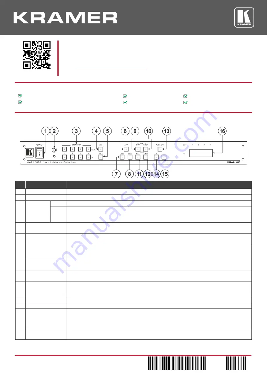
Step 2: Get to know your VP-4x4K
#
Feature
Function
1
POWER Switch
Illuminated switch for turning the unit ON or OFF
2
IR Receiver
Signals from the remote control transmitter illuminate the LED
3
SELECTO
R Buttons
OUT
Select the output to which the input is switched
IN
Select the input to switch to the output
When a signal is detected, the input button illuminates in green
The SELECTOR IN and OUT buttons also store/recall the input/output configurations
4
ALL Button
Pressing ALL before pressing an input button connects that input to all outputs
For example, press ALL and then Input button # 2 to connect input # 2 to all the outputs
5
OFF Button
Pressing OFF after pressing an output button disconnects that output from the inputs. To disconnect
all the outputs, press the ALL button and then the OFF button
6
AFV Button
When illuminated, the audio channels follow the video channels. The button is illuminated when the
AFV mode is selected. If the AUDIO differs from the VIDEO, the TAKE button will flash, and you
have to press the TAKE button to confirm the modification
7
VID Button
When illuminated, actions relate to video
The VID button is illuminated when in breakaway mode and actions relate to video
8
AUD Button
When illuminated, actions relate to audio
The AUD button is illuminated when in breakaway mode and actions relate to audio
9
STO Button
Pressing STO (STORE) followed by an output
or an input button stores the current setting
Press the STO and LOCK buttons simultaneously to set the delay time. For example, press STO and
then the Output button # 3 to store in Setup # 3
10
LOCK Button
Disengages the front panel switches
11
RCL Button
Pressing RCL (RECALL) followed by an output or an input button displays a stored setup
12
TAKE Button
Pressing TAKE toggles the mode between the CONFIRM mode and the AT ONCE mode (user
confirmation per action is unnecessary). When in CONFIRM mode, actions are confirmed by
pressing the TAKE key. For example, press STO and then the Output button # 3 to store in Setup # 3
When in the CONFIRM mode, the TAKE button illuminates
13
AUDIO GAIN
Button
Press to adjust the audio input or output gain


