


Using Your Universal Room Controller
5
Ethernet Port
Side View
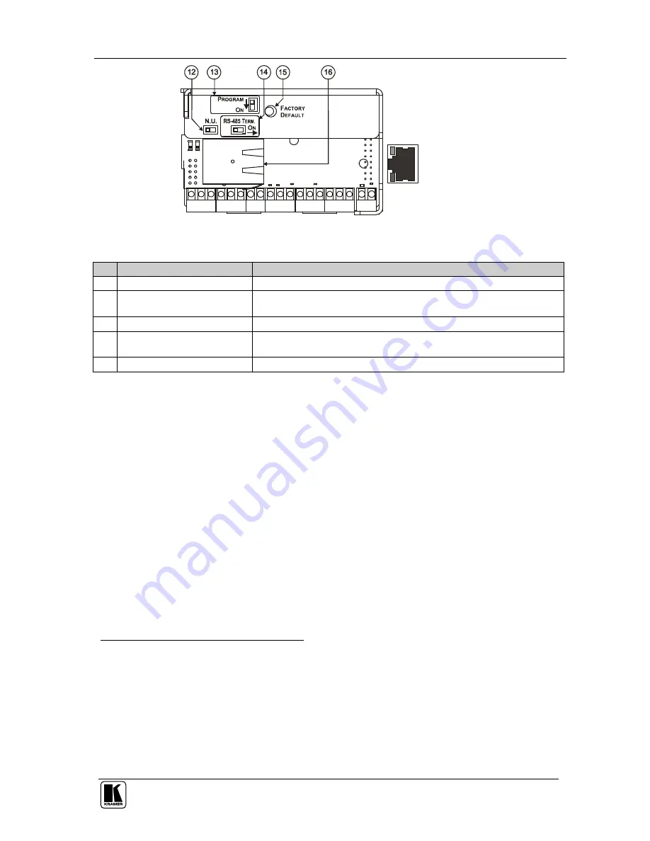
Figure 3: RC-8IR and RC-6IR Rear Panel
Table 3: RC-8IR and RC-6IR Rear Panel Features
#
Feature
Function
12
N.U
Switch
Not used
13
PROGRAM
Switch
Switch to OFF for normal operation;
Switch to ON for firmware upgrade
14
RS-485 TERM.
Switch
Switch to ON for RS-485 line termination
15
FACTORY DEFAULT
Button
Press to return to the factory default settings, including all the configured
buttons and the network settings
1
16 Ethernet Port
Connects to a PC or other controller through computer networking
5 Using Your Universal Room Controller
2
This user manual is applicable once the unit is installed and configured
3
. The
installation process is not detailed in this user manual
4
, and includes:
Setting up the labels on the buttons, according to your specific
requirements
5
Hardware installation
Connecting the inputs and the display
Configuration via the Windows®-based configuration software and/or
the IR learner
The universal room controller is very easy to use, as the example in Figure 4
and Table 4 defines
6
:
1 Including the factory default IP number: 192.168.1.39 (an IP number is a device's numerical address as expressed in the
format specified in the Internet Protocol)
2 From this section on, all the information is relevant to the RC-6IR and RC-8IR units, unless noted otherwise
3 By authorized Kramer technical personnel or by an external system integrator
4 Refer to the separate online “RC Configuration and Installation Guide” at http://www.kramerelectronics.com
5 It is recommended to place labels on the buttons prior to installing the unit, as this involves removing the face plate
6 Your RC-8IR was installed and configured to suit your specific requirements. This example describes how to setup one of
an unlimited number of available setups for the system


