background image

Using Your FC-7402 SDI to Analog Converter 


3

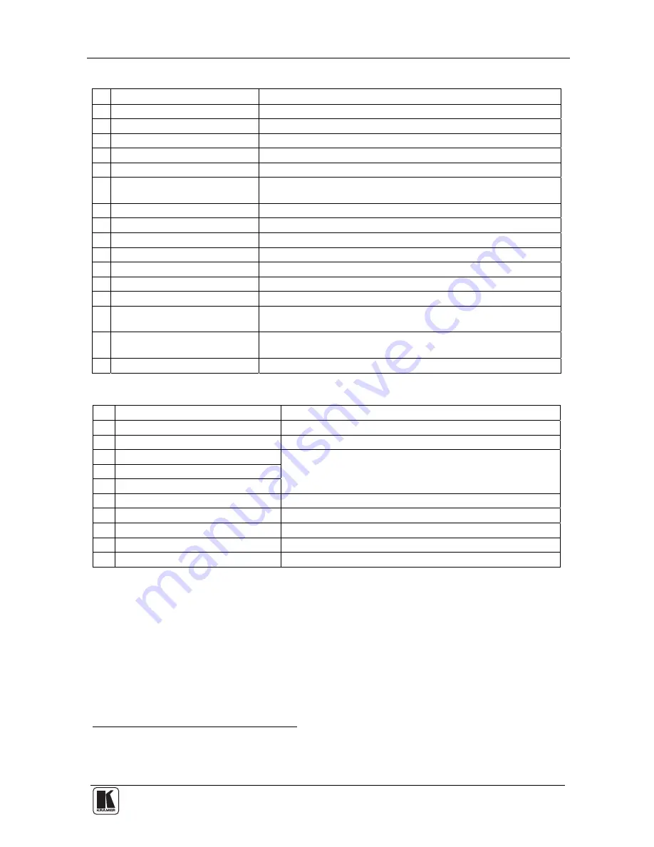
Table 1: Front Panel FC-7402 SDI to Analog Converter 

# Feature 

Function 

POWER Switch 

Illuminated switch supplying power to the unit 

HUE Button 

Press the HUE button and adjust using the + and – buttons 

CONT (CONTRAST) Button 

Press the CONT button and adjust using the + and – buttons 

BRIGHT (BRIGHTNESS) Button  Press the BRIGHT button and adjust using the + and – buttons 

SHARP Button 

Press the SHARP button and adjust using the + and – buttons 

COLOR Button 

Cycles between SATURATION, R-Y, and B-Y. The corresponding 
LED lights 

SATURATION LED 

Lights after selecting SATURATION via the COLOR button 

R-Y LED 

Lights after selecting R-Y via the COLOR button 

B-Y LED 

Lights after selecting B-Y via the COLOR button 

10  STO Button 

Stores the current setup in the non-volatile memory 

11  RCL Button 

Recalls a setup from the non-volatile memory 

12  - Button 

Press to decrease 

13  + Button 

Press to increase 

14  7-segment Display 

Displays data when using a front panel button; briefly displays 

firmware version when machine is turned on 

15  PANEL LOCK LED 

Illuminates when the panel is locked (blinks after pressing a button 

when the panel is locked) 

16  PANEL LOCK Button 

Engages/disengages the front panel buttons 

Table 2: Rear Panel FC-7402 SDI to Analog Converter 

# Feature 

Function 

SDI IN BNC Connector 

Connects to the SDI source 

SDI OUT BNC Connector 

Connects to the reclocked and equalized SDI acceptor 

Y / G OUTPUTS BNC Connector 

B-Y / B OUTPUTS BNC Connector 

R-Y / R OUTPUTS BNC Connector 

 
Connects to the RGB

1

 or component

2

 video acceptor 

YC OUTPUT 4p Connector 

Connects to the s-Video (Y/C) output 

CV OUTPUTS BNC Connector 

Connects to the composite video output 

Dipswitches 

Dipswitches setup (see section 


5.1.2) 

RS-232 Port 

Connects to the PC or the Remote Controller 

10  Power Connector with Fuse 

AC connector enabling power supply to the unit 

5  Using Your FC-7402 SDI to Analog Converter 

You can use your FC-7402, to convert SDI video to professional quality 
analog video—composite video, s-Video and component

3

 (YUV or RGB) 

video—as the example in Figure 2 illustrates. 


1 For RGB video, connect all 3 connectors: G, B, and R 

2 For component video, connect all 3 connectors: Y, B-Y, and R-Y 

3 Y, B-Y, R-Y is also known as Y, Pb/Cb, Pr/Cr, or YUV or Y, Pb, Pr 

Summary of Contents for FC-7402

Page 1: ...Kramer Electronics Ltd USER MANUAL Model FC 7402 SDI to Analog Converter...

Page 2: ...6 Technical Specifications 9 7 Communication Protocol 10 Figures Figure 1 FC 7402 SDI to Analog Converter 2 Figure 2 Connecting an FC 7402 SDI to Analog Converter 4 Figure 3 Connecting a PC without u...

Page 3: ...original box and packaging materials for possible future shipment Review the contents of this user manual Use Kramer high performance high resolution cables3 3 Overview The high quality FC 7402 is a m...

Page 4: ...r friendly Windows based program that can modify parameters such as hue contrast brightness sharpness and color Lets you store recall up to 10 setups in non volatile memory To achieve the best perform...

Page 5: ...achine is turned on 15 PANEL LOCK LED Illuminates when the panel is locked blinks after pressing a button when the panel is locked 16 PANEL LOCK Button Engages disengages the front panel buttons Table...

Page 6: ...osite video monitor 3 Connect the Y C OUTPUT 4p connector to an s Video acceptor for example an s Video monitor 4 Connect the component video OUTPUT BNC connectors Y G B Y B and R Y R to either a YUV...

Page 7: ...to the Null modem adapter and connect the Null modem adapter with a 9 wire flat cable to the RS 232 DB9 port on your PC To connect a PC to the FC 7402 unit without using a Null modem adapter Connect...

Page 8: ...ndard see Table 4 8 BAR ON for machine to operate as a 75 color bar generator based on the clock of the SDI input Table 4 Dipswitch Settings AUTO PAL and NTSC AUTO PAL NTSC FC 7402 Output Standard OFF...

Page 9: ...o 2 X OVRSMPL To adjust oversampling to x2 do the following 1 Set DIP 4 OFF and remove the power cord 2 Open the FC 7402 unit and move Jumper JMP1 to the left see Figure 4 3 Close the FC 7402 unit set...

Page 10: ...l by one unit The 7 segment display shows the new level Note To increase or decrease the current level rapidly press and hold down the button or button continuously2 To end the rapid adjustment releas...

Page 11: ...ideo 1Vpp 75 on a BNC connector 1 YC 1Vpp 75 Luma 0 3Vpp 75 Chroma on a 4p connector 1 component RGB Y R Y B Y 1V 0 7V 0 7V 75 on BNC connectors 1 SDI reclocked SMPTE 259M ITU R BT 601 CCIR 601 75 on...

Page 12: ...ATA D7 and the EXTENDED DATA E7 are in the fourth byte Terminology TO PC is the DESTINATION BIT I4 I0 is the INSTRUCTION D7 D0 is the DATA E7 E0 is the EXTENDED DATA The destination bit TO PC is 0 whe...

Page 13: ...s instruction then if valid the selected video parameter is set and the machine replies by sending the same 4 bytes except for the Destination Bit back to the PC When the user changes video parameters...

Page 14: ...e set for a fixed standard the FC 7402 will reply by sending the code for the fixed standard INSTRUCTION 16dec ERROR If the machine receives an invalid instruction it replies by sending this error cod...

Page 15: ...riginal dated invoice or a copy must be presented as proof of warranty coverage and should be included in any shipment of the product Please also include in any mailing a contact name company address...

Page 16: ...E mail info kramerel com P N 2900 007402 REV 1 For the latest information on our products and a list of Kramer distributors visit our Web site www kramerelectronics com Updates to this user manual may...

Reviews: