

Step 3: Install the FC-7
You can mount this Kramer Pico
TOOL™ next to a USB power source behind an
AV device, within the ceiling, on a desk top, wall or similar area. Fasten a bracket
on each side of the TOOLS using the two M3x8 screws (supplied). Use the flat-
head screws (supplied) to fix the TOOL to the mounting surface or enable it to
slide in place.
Or you can attach the rubber feet and place on a table or mount the
FC-7
in a rack
(using an optional
RK-3T
rack mount).
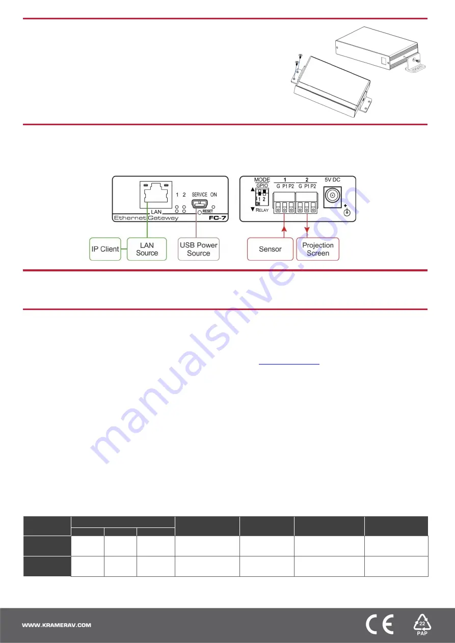
Step 4: Connect the inputs and outputs
Always switch OFF the power on each device before connecting it to your
FC-7
. For best results, we recommend that you always
use Kramer high-performance cables to connect controlled equipment to the
FC-7
.
Step 5: Connect the power
Connect a USB power source and/or an optional 5V DC power supply to the
FC-7
and plug it into the mains electricity.
Step 6: Configure and operate the FC-7
Note
: The
FC-7
is shipped from the factory with DHCP enabled and a random IP address. To connect the
FC-7
on first installation,
you must identify what IP address has been automatically assigned to the
FC-7
. To discover the IP address of
FC-7
, use
K-LAN Configurator
, available for download from our website at
To reset the device to its factory default settings
:
1. Turn off the power to the device.
2. Press and hold the Reset button on the front panel.
3. Turn on the power to the device while holding down
the Reset button for a few seconds.
4. Release the button.
The device is reset to the factory default settings.
To browse the FC-7 Web UI (User Interface) using
factory default settings:
Use the default host name:
FC-7-xxxx
, where xxxx are
the last four digits of the serial number of the device
.
FC-7 Function Table
To configure and operate the
FC-7
:
1. Using the device Web UI, configure the control gateway:
• Set DHCP or assign a static IP address
• Associate IP port(s) with the relevant port(s)
• Configure the relevant port parameters
2. Configure IP client connection port(s) on a Kramer control or
any other control software application.
3. Set the control application to use the control gateway ports for
sending and receiving control communication over the IP
connections.
Key:
P1 / P2
– Port 1 / Port 2; IO
1
/ IO
2
– GPIO Port 1 / GPIO Port 2;
NO
1
/
NO
2
– Normally open Port 1 / Normally open Port 2
Port IO
Function
Terminal Block Connections
IO Port Default
TCP Default
Port [P1/P2]
Activity LEDs
P1-white P2-blue
Comment
G
P1
P2
GPIO
Ground
IO
1
IO
2
Digital In x 2
5000
ON when IO
ports are active
GPIO Analog in &
Digital out via Web
Relay
Common
NO
1
NO
2
Normally Open x 2
5000
ON when Relay
ports are active


