


8
DS Vision® 3000 - Overview
3.5
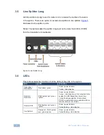
Line Splitter Long
Add line splitters L(ong) to use for clusters or to increase the number of receivers
in the system. There is an option to cascade line splitters to line splitters.
Figure 5
illustrates the line splitter L ports.
Notes: The last cascaded line splitter long must not be more than 300m (1000ft)
from the transmitter or broadcaster.
Figure 5: Line Splitter Long
3.6
LEDs
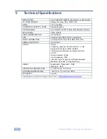
This table explains the functions of all the LEDs of the units in the system.
Unit
LED
Function
Transmitter /
Broadcaster
Front panel - green
Green - power indicator
Yellow – link indication
Receiver /
Receiver L
RJ-45 system port - green
/yellow
Green - power indicator
Yellow – link indication, unit is connected to the
system this LED flashes from time to time
Yellow flashing constantly – Bi-directional
RS-232 communication (only possible with one
receiver /receiver L at a time)
Receiver DCL
RJ-45 system port - green
/yellow
Green - power indicator
Yellow flashing – link indication
Line Splitter L
Rear panel – RJ-45 system
port - green /yellow
Green - power indicator
Yellow flashing – link indication


