6
ASSEMBLY INSTRUCTIONS
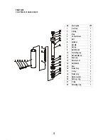
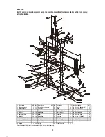
Use the exploded drawing as your guide to assemble. Lay all parts and assemblies out in front of you
before beginning. The following procedure is recommended:
• Attach one base support (02) to left post and lower connecting base (01) using spring washers (05),
nuts (06), screw bolts (07) washers (04), then attach another to right post and the lower connecting base.
• Fix one end of support beam B (09) to the base support (02) and another end to the connecting base
(01) using spring washers (05), nuts (06), screw bolts (07) and washers (04).
• Put another upper crossbeam into position and insert the under plate (29) to the two upper cross
beams at the same time, then secure this cross beam to the posts using spring (22) and screw bolts (23).
• Screw the upper round nut onto the press cylinder (24), insert the press cylinder into the hole in the
under plate (29), then screw the under round nut onto the press cylinder and attach the serrated saddle
to the press cylinder.
• Insert bed frame pin (34) into the holes in the posts, then insert the joined press bed frame (33) into
press frame and onto bed frame pin.
• Attach the hydraulic pressure pump (11) to the right post using screw bolts (36), spring washers (37).
then insert the handle to the handle bracket.
• Connect the hose fitting (14) to the press cylinder (24) and assemble the press gauge (27) to the
pressure gauge connection nut which is on the top of hose fitting (14).
• Tighten all bolts and screws.
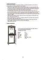
PRODUCT DESCRIPTION
- Lateral movable cylinder with bearing (moving range: 200 mm)
- Pressure gauge with integrated housing
- Including par of V-blocks
Capacity: 30 t
Stroke: 150 mm
Work range: 1100 mm
Work width: 550 mm
Stamp-Ø: 53 mm
Product size: 1840 x 885 x 700 mm
N.W.: 165 kg
53 mm
550 mm

