background image

VENTING 

29

7.9  #700-2 Series Direct Vent 

Termination Kit(s)

IMPORTANT: The vertical vent heat shield included with 
this fireplace must be installed for every type of top venting 
application. The horizontal vent heat shield must be installed 
when incorporating minimum horizontal venting off the top.
IMPORTANT: The flex pipe is permanently attached to the 
exterior plate. DO NOT ATTACH either #745-2 or #718-2 
termination kit to fireplace (or extension kit) until it has passed 
through the wall. Install termination plates to the outside wall 
exterior.
IMPORTANT: The minimum bend radius to center is 6 in (152 
mm) required for installation of the flexible vent pipe. Care 
should be taken when installing to avoid a tight bend that may 
cause abrasion or damage to the flexible pipe.

•  If terminating against vinyl siding, a vinyl siding protector 

must be used (included with the #745-2 and #718-2 direct 
vent kits). Follow instructions included. 

•  Each #746-2 extension kit contains enough 4” & 7” flexible 

aluminum pipe to extend chimney an additional 6 ft (1.83 m). 

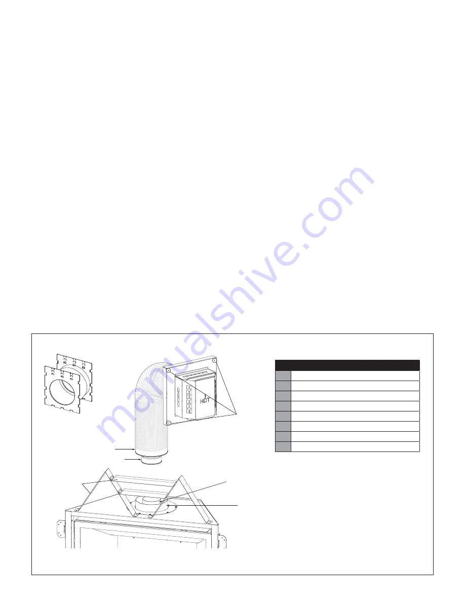
7.9.1  Assembly and Installation

1.  Attach vinyl siding protector (G) (not shown).
2.  Mount the required wall thimble (H) with 1 in (25 mm) top 

clearance and 1 in (25 mm) side clearance to the exterior 
wall, and seal. 

(OPTIONAL) insulate the wall thimble with any unfaced 
insulation products listed as non-combustible per ASTM E 
136.

3.  Apply a liberal bead of exterior sealant around outer edge of 

termination box (A), placing assembly through the wall-pass 
through in exterior wall. Place screws through the four holes 
(B), securing it in place.

4.  Form the 4” & 7” flexible aluminum pipes on termination kit 

(#745-2 or #718-2), and if applicable, on each extension kit. 

5.  Gently pull 4” & 7” pipes down to the top of the fireplace, or if 

applicable, the extension kit.  

IMPORTANT: DO NOT stretch extension kit beyond 6 ft. 
(1.83 m); DO NOT stretch beyond what is required. It is 
very difficult to decompress flex pipes once stretched. 

6.  Place a bead of sealant outside 4” flex pipe collar (C) (end 

with EXTERNAL LIP) and sliding it into 4” pipe on extension 
kit or top of fireplace (D). Secure with 3 evenly spaced 
screws.

7.  Place a bead of sealant inside 7” flex pipe collar (E) (end 

with the INTERNAL lip), sliding it over 7” pipe on top of 
fireplace (F). Secure with 3 evenly spaced screws. 

8.  If additional extension kits are required, repeat Steps 4 and 

5, placing 4” & 7” pipes onto previous extension kit.

LEGEND

A

Termination box

B

Holes in exterior wall plate (only 3 shown)

C

4” flex pipe collar

D

4” pipe on fireplace or extension kit 

E

7” flex pipe collar

F

7” pipe on fireplace or extension kit

G

Vinyl firestop (not shown)

H

Wall Thimble with 1 in (25 mm) top clearance

Figure 7.8, Installation and Assembly of #700-2 Series (Vent Heat Shield Assembly not shown for clarity purposes only) 

C

E

H

F

D

STAND-OFFS

A

B

#700-WPT

Summary of Contents for BAY-36-L

Page 1: ...e home where not prohibited by local codes This appliance is only for use with the type of gas indicated on the rating plate This appliance is not convertible for use with other gases unless a certified kit is used INSTALLER Leave this manual with the appliance CONSUMER Retain this manual for future reference BAYPORT 36 LOG Model BAY 36 L Direct Vent Gas Fireplace Tested Listed By OMNI Test Labora...

Page 2: ......

Page 3: ...er safety We offer our continual support and guidance to help you achieve the maximum benefit and enjoyment from your Kozy Heat gas fireplace Jim Hussong President Dudley Hussong Board Chairman Homeowner Reference Information We recommend you record the following information Model Name ____________________________________________ Serial Number ___________________________________________ Dealership...

Page 4: ......

Page 5: ...rsion Instructions 22 7 2 Approved 4 x 65 8 Vent Systems 24 7 3 Venting Requirements 24 7 4 Use of Elbows 24 7 5 Restrictor Assembly and Installation 24 7 6 Top Venting 25 7 7 Vent Heat Shield Assembly Installation 26 7 8 Rear Venting 27 7 9 700 1 Series Direct Vent Termination Kit s 29 8 0 FIREPLACE SETUP 30 8 1 Glass Frame Assembly 30 8 2 B36 500 Log Set Installation 31 8 3 Control Board Removal...

Page 6: ......

Page 7: ...the above provisions shall comply with NFPA 720 and be ANSI UL 2034 listed and IAS certified 1 2 3 Signage A metal or plastic identification plate shall be permanently mounted to the exterior of the building at a minimum of eight 8 feet above grade directly in line with the exhaust vent terminal for the horizontally vented gas fueled heating appliance or equipment The sign shall read in print no l...

Page 8: ...sure High 3 8 WC 0 95 kPa 11 WC 2 74 kPa Manifold Pressure Low 1 1 WC 0 27 kPa 2 9 WC 72 kPa Orifice Size DMS 43 53 2 2 1 Altitude Adjustment This appliance may be installed at higher altitudes Please refer to National Fuel Gas Code ANSI Z223 1 NFPA 54 CSA B149 1 Natural Gas and Propane Installation Code local authorities or codes having jurisdiction in you area regarding derate guidelines 2 2 1 1...

Page 9: ...o Rear Vent Center Inches 32 35 3 4 18 7 8 15 13 16 32 5 8 26 13 16 10 7 7 8 25 7 8 Millimeters 813 907 479 401 829 681 254 199 657 Figure 2 1 Bayport 36 Unit Dimensions 18 7 8 479mm 7 7 8 199mm 15 13 16 401mm 10 254mm 26 13 16 681mm 32 813mm 32 5 8 829mm 35 907mm 8 3 16 208mm 2 5 16 58mm 25 7 8 657mm 5 15 16 152mm 1 15 16 49mm TOP FRONT LEFT SIDE RIGHT SIDE ELECTRICAL ACCESS GAS LINE HOLE ...

Page 10: ...to be level with finished hearth For installation instructions refer to Section 4 4 Safety Barrier Installations on page 18 TOP AND SIDES OVERLAP NO OVERLAP INSIDE FIT TOP AND SIDES OVERLAP TOP AND SIDES OVERLAP TOP AND SIDES OVERLAP TOP AND SIDES OVERLAP TOP AND SIDES OVERLAP B36 PSF B36 FRSF B36R MSF B36A MSF B36R CSF B36 RSF B36A FPDSF 36 3 8 924mm 32 819mm SIDE OVERLAP TOP OVERLAP SIDE OVERLAP...

Page 11: ...idth of the fireplace DO NOT use wood sheetrock et cetera in this zone Top stand off brackets must be formed and attached prior to positioning fireplace into framed opening NOTE If installing trim kit assembly B36 FTK please refer to Section 4 3 Optional Trim Kit Assembly B36 FTK on page 17 before installing stand offs 1 Remove and save 4 screws securing stand off heat shields and stand off bracke...

Page 12: ...157 8 403mm 1 25mm 26 673mm 1 25mm 507 16 1280mm 36 920mm 117 8 301mm 6mm 2411 16 628mm 355 8 905mm 36 920mm 157 8 403mm 36 920mm 157 8 403mm 36 920mm INCLUDES TYPICAL FINISH MATERIAL WITH FLUSH MOUNT DIMENSION SHOWN WITH LISTED DURAVENT ELBOW NOTE Approved vent system elbows for this appliance vary in vertical length Consult vent manufacturer s instructions to determine the elbow dimension used f...

Page 13: ...If using a hearth adjust the rough opening size as necessary to maintain minimum clearance requirements If masonry is to be used optional prepare the necessary foundation for the masonry load When masonry construction is to be used a lintel must be used over the top of the appliance to support the additional weight Figure 3 3 Finished Opening Dimensions 42 1067mm 36 920 mm 157 8 403mm SINGLE VERTI...

Page 14: ...ces as outlined in this manual and be constructed in compliance with local building codes Outside walls should be insulated to prevent cold air from entering room Follow vent pipe manufacturer s installation instructions for vertical terminations A minimum of 1 in 25 mm clearance on all sides of the vertical vent pipe must be maintained Attic insulation shields may be insulated using unfaced insul...

Page 15: ...s facing away from the fireplace 3 Secure the nailing flanges to the fireplace with screws provided through the slots in nailing flanges 4 Bend perforation on nailing flange until parallel with fireplace face Do not bend toward fireplace face 5 Position framing stud against the small stand off located on backside of nailing flange Secure with nails or screws When installed the nailing flanges prov...

Page 16: ...y high temperatures emitted from this appliance To help avoid or reduce the possibility of the sheetrock to crack Hussong Mfg recommends the following methods Ensure the non combustible material and sheetrock is dry and dust free For taping and mudding seams we recommend heat resilient tape mesh and joint compounds such as Durabond Mud must be cured as per manufacturer s recommendations For a pain...

Page 17: ...d as shown below Secure with 2 screws included in the fireplace components packet 3 If installed remove the top stand offs 4 Install the top trim panel Align the holes in the top trim panel with the front holes in the stand offs and attach to the fireplace top Secure with the screws previously removed and included in the components packet 5 If installed remove the nailing flanges from the sides of...

Page 18: ...n but do not remove the 4 truss head screws located on the sides of the fireplace Raise the screen up slightly and out 4 4 2 Overlap Fit Hanging Installation Models B36 PSF B36 FRSF B36R MSF B36A MSF B36R CSF and B36A FPDSF 1 Center the screen front over the glass frame assembly allowing the screen front s mounting brackets to fit inside the air openings 2 Align the notched tabs located on the bac...

Page 19: ...essures in excess of psi 3 5 kPa For test pressures equal to or less than psi 3 5 kPa the appliance must be isolated from the gas supply piping system by closing its individual manual shut off valve A listed and Commonwealth of Massachusetts approved in 13 mm tee handle manual shut off valve and flexible gas connector are to be connected to the in 13 mm control valve inlet If substituting for thes...

Page 20: ...7 12 1 25 0 38 Over 7 12 to 8 12 1 5 0 46 Over 8 12 to 9 12 2 0 0 61 Over 9 12 to 10 12 2 5 0 76 Over 10 12 to 11 12 3 25 0 99 Over 11 12 to 12 12 4 0 1 22 Over 12 12 to 14 12 5 0 1 52 Over 14 12 to 16 12 6 0 1 83 Over 16 12 to 18 12 7 0 2 13 Over 18 12 to 20 12 7 5 2 27 Over 20 12 to 21 12 8 0 2 44 12 x H H LOWEST DISCHARGE OPENING APPROVED CAP APPROVED VENT PIPE ROOF PITCH x 12 H MINIMUM HEIGHT ...

Page 21: ...cm 9 in 23 cm K Clearance to mechanical air supply inlet 6 ft 1 83 m 3 ft 91 cm above if within 10 ft 3 m horizontally Massachusetts 10 ft 3 m L Clearance above paved sidewalk or paved driveway located on public property 7 ft 2 13 m M Clearance under veranda porch deck or balcony 12 in 30 cm 12 in 30 cm N Clearance between two horizontal terminations 12 in 30 cm 12 in 30 cm O Clearance between two...

Page 22: ...l components removed from the top vent exit will be reinstalled for the rear vent 7 1 1 Remove Top Vent Collars 7 1 2 Remove Back Vent Combustion Air Intake and Exhaust Collars 1 REMOVE 7 SCREWS SECURING COVER PLATE 2 REMOVE 4 SCREWS SECURING 6 168mm COMBUSTION AIR INTAKE COLLAR 3 REMOVE 6 SCREWS SECURING 4 101mm EXHAUST COLLAR 1 REMOVE 5 ATTACHMENT SCREWS SECURING BACK COVER PLATE 2 REMOVE 4 SCRE...

Page 23: ... GASKET IS IN PLACE UNDERNEATH SECURE WITH 6 SCREWS PREVIOUSLY REMOVED 2 INSTALL 6 168mm COMBUSTION AIR INTAKE COLLAR TO REAR VERIFY GASKET IS IN PLACE SECURE WITH 4 SCREWS PREVIOUSLY REMOVED 3 SECURE COVER PLATE WITH 5 SCREWS PREVIOUSLY REMOVED 1 INSTALL EXHUAST COVER PLATE TO FIREPLACE TOP VERIFY GASKET IS IN PLACE SECURE WITH 6 SCREWS PREVIOUSLY REMOVED 2 INSTALL COMBUSTION AIR INTAKE COVER PLA...

Page 24: ...vent runs that pass through interior or exterior walls These wall thimble products may be insulated using unfaced insulation products listed as noncombustible per ASTM E 136 NOTE Attic insulation shields may be insulated using unfaced insulation products listed as noncombustible per ASTM E 136 Table 7 1 Vertical Pipe Section Clearances Surface Sides All Approved Venting 1 in 25 mm Table 7 2 Horizo...

Page 25: ...ation Venting Table 7 4 NG LPG Minimum Horizontal Vent Terminations Minimum Vertical Venting Minimum Horizontal Run HMIN Maximum Horizontal Run HMAX 90 elbow 6 in 152 mm 8 ft 2 4 m Table 7 5 NG LPG Max Vertical Max Horizontal Combination Maximum Vertical Rise Maximum Horizontal Run Total Length 25 ft 7 6 m 25 ft 7 6 m 50 ft 15 2 m Maximum number of 90 elbows 5 Figure 7 2 NG LPG Top Vent Combinatio...

Page 26: ...s with corresponding screw holes located in front of the flue outlet on the top of the fireplace 3 Secure the vertical vent heat shield to the fireplace with 2 attachment screws provided in the components package 7 7 2 Minimum Horizontal Venting 1 Bend perforation on the 3 hand tabs down on the horizontal vent heat shield 2 Locate 3 screw holes on the vertical vent heat shield 3 Align the 3 slots ...

Page 27: ...nimum Vertical Length Maximum Vertical Length 90 elbow 3 ft 914 mm 50 ft 15 2 m Table 7 8 NG Max Vertical Max Horizontal Combination Maximum Vertical Rise Maximum Horizontal Run Total Length 25 ft 7 6 m 25 ft 7 6 m 50 ft 15 2 m Maximum number of 90 elbows 5 Figure 7 6 NG Rear Vent Combination Venting H V REAR VENTING DIAGRAM VERTICAL HORIZONTAL TERMINATIONS A Stand off Brackets B Stand off Heat Sh...

Page 28: ...cal Length Maximum Vertical Length 90 elbow 3 ft 914 mm 50 ft 15 2 m Table 7 11 LPG Max Vertical Max Horizontal Combination Maximum Vertical Rise Maximum Horizontal Run Total Length 25 ft 7 6 m 25 ft 7 6 m 50 ft 15 2 m Maximum number of 90 elbows 5 REAR VENTING DIAGRAM VERTICAL HORIZONTAL TERMINATIONS A Stand off Brackets B Stand off Heat Shields C 90 Elbow D Vertical Vent Heat Shield not applicab...

Page 29: ...insulation products listed as non combustible per ASTM E 136 3 Apply a liberal bead of exterior sealant around outer edge of termination box A placing assembly through the wall pass through in exterior wall Place screws through the four holes B securing it in place 4 Form the 4 7 flexible aluminum pipes on termination kit 745 2 or 718 2 and if applicable on each extension kit 5 Gently pull 4 7 pip...

Page 30: ...ng loaded latches securing the glass assembly at the bottom of the firebox 2 Pull the spring loaded latches out and down to release the bottom of the glass assembly 3 Life glass assembly up and off of the 2 tabs located at the top of the firebox 8 1 2 Install Glass Frame Assembly 1 Align the slots on top of the glass assembly over the tabs at the top of the firebox while lowering the bottom of the...

Page 31: ...uctions included with the kit Log numbers are located on the bottom of each log Refer to the following instructions and illustrations for proper log placement 1 Position the ember panel in front of the burner 2 Align the holes in the bottom of base logs B36 1 to B36 4 with the mounting pins on the burner Push logs down onto pins to seat 3 Align logs B36 5 and B36 6 with the notches on base logs 4 ...

Page 32: ...burner assembly 2 screws on each side 8 Remove the burner heat shield 3 screws located at the back of the firebox 9 Remove and save 8 screws securing the control board 10 Lift the control board out of the firebox being careful not to damage the sealing gasket underneath 8 3 2 Control Board Installation 1 Place control board in the firebox aligning the holes in the control board with the holes in t...

Page 33: ...ut or remove the grounding prong from this plug 9 1 Electrical Specifications This appliance when installed must be electrically grounded in accordance with local codes or in the absence of local codes with the National Electrical Code ANSI NFPA 70 or the Canadian Electrical Code CSA C22 1 9 2 Wiring Requirements The IFC System Module requires 120V of electricity and or batteries to operate Using ...

Page 34: ...ht bar through the grommet 6 Remove and save the 2 light kit mounting bracket screws on the control board Install mounting bracket using 2 screws previously removed 7 Connect the light wires to the light lead wires on the IFC module Apply high temperature sealant around the grommet and wires to create an air tight seal 8 Secure the light housing with 2 screws included 9 Install 4 halogen bulbs int...

Page 35: ...e appliance will not operate follow the instructions To Turn Off Gas To Appliance and call your service technician or gas supplier OPERATING INSTRUCTIONS NOTE When this fireplace is initially lit condensation will appear on the glass This is normal in all gas fireplaces and will disappear after several minutes A paint smell will occur during the first few hours of burning It is recommended to leav...

Page 36: ...position for remote control operation of the main burner and fireplace features 10 3 Reset the System for Manual Operation 1 Set the ON OFF rocker switch to OFF position 2 Press the red SWI button on the IFC module until it emits 3 beeps and an amber LED is illuminated 3 Within 5 seconds press the red SWI button again This will close synchronization with the remote control The pilot will automatic...

Page 37: ...ximately 2 seconds move the switch to the ON position The ignition sequence will start again 10 6 1 2 Remote Control ON OFF Key 1 Press the remote control ON OFF key to turn the system OFF 2 After approximately 2 seconds press the ON OFF key again The ignition sequence will start again 10 6 1 3 Cycling Flame 1 Press the remote control down arrow key during flame adjustment mode to reduce the flame...

Page 38: ... standing pilot option The standing pilot will keep the firebox warm and establish a draft in the vent which allows the main burner to ignite with less air flow disruption When the system is OFF the LCD screen will display the snowflake icon during the setup of either IPI or CPI mode To select the preferred pilot ignition feature 1 With the system in the OFF position press the mode key to index th...

Page 39: ...t can be set to a desired temperature to control a room s comfort level To activate this function 1 Press the thermostat key The LCD screen will display a temperature bulb graphic the room temperature and set temperature 2 To adjust the set temperature press the up or down arrow keys until the desired temperature is displayed on the LCD screen 10 8 7 2 Smart Thermostat The smart thermostat functio...

Page 40: ...e Fan s will operate at previous setting There is no delay in start up or stop time 10 8 9 Accent Light Kit if applicable The light intensity can be adjusted through 6 levels 1 Press the mode key to index to the light icon 2 Press the up or down arrow keys to adjust the intensity level 3 A single beep will confirm reception of the command 10 8 10 Remote Control Low Battery Detection Remote control...

Page 41: ...aximum recommended pressure settings 4 Turn off burner and pilot 5 Disconnect hose and tighten the inlet IN pressure tap by turning screw clockwise Screw should be snug Do not over tighten 6 Relight pilot and burner Then reattach manometer to the inlet pressure tap A to verify the tap is completely sealed Manometer should read no pressure 11 1 2 Manifold Pressure Test 1 Light pilot 2 Loosen manifo...

Page 42: ...le 11 3 Factory Set Venturi Openings Fuel Air Shutter Opening Natural Gas 1 8 3 mm OPEN LP Gas 5 8 15 mm OPEN 11 2 1 1 Venturi Adjustment NOTE If soot is present on the glass check log positioning before adjusting the venturi Logs must not block burner ports 1 Remove the safety barrier and glass frame assembly 2 Remove the log set the back log plate burner assembly and burner heat shield from the ...

Page 43: ... 1 Restrictor Installation 1 Remove the safety barrier and glass frame assembly 2 Remove 4 screws securing baffle Remove baffle to expose venting 3 Bend the tabs on the restrictor included in fireplace components packet to approximately 80 angles This will create tension when the restrictor is inserted into the exhaust pipe 4 Insert restrictor into the 4 in 102 mm exhaust pipe with the tabs pointi...

Page 44: ... propane gas in tank Check LP propane tank Refill if necessary Low gas pressure Consult a plumber or a gas supplier Can be caused by situations such as a bent line too narrow diameter or pipe or a low line pressure Pilot flame not making contact with the flame rectification sensor on the pilot assembly Verify the pilot flame envelopes the top of the flame sensor and extends far enough onto burner ...

Page 45: ...1 Improper venturi setting Venturi air shutter may need to be opened slightly to allow more air into the gas mix Refer to Section 11 2 1 Burner Venturi on page 42 Incorrect vent cap installation Adjust if necessary Vent cap blockage Remove debris if necessary Flame burns blue and lifts off burner Improper venturi setting Venturi air shutter may need to be opened slightly to allow more air into the...

Page 46: ... sealed and require no oiling 13 3 Vent System NOTE If the vent air intake system is disassembled for any reason reinstall per instructions provided with installation Refer to Section 7 0 Venting on page 22 Performed by Qualified Service Person Frequency Annually Action Examination of the vent system is required The flow of combustion and ventilation air must not be obstructed 13 4 Glass Assembly ...

Page 47: ...sembly LPG 700 551 1 Conversion Kit LPG LCK B36L S Transmitter Remote Control 700 408 Log Plate B36 351 Pilot Orifice NG 62 700 166 Light Kit Mounting Bracket B36 LKHS Pilot Orifice LPG 35 700 168 Hussong Manufacturing Co Inc P O Box 577 204 Industrial Park Drive Lakefield MN 56150 0577 USA BAY 36 L LOG SET 8 Piece Log Set B36 500 Ember Panel B36 900E B36 1 Log B36 1 B36 2 Log B36 2 B36 3 Log B36 ...

Page 48: ......

Page 49: ...ong Manufacturing Co Inc s behalf any additional obligation of liability connected with the unit It is expressly agreed and understood that this warranty is Hussong Manufacturing Co Inc s sole obligation and purchaser s exclusive remedy for defective fireplace equipment Hussong Manufacturing Co Inc shall not be liable for any consequential incidental or contingent damages whatsoever The foregoing ...

Page 50: ......

Page 51: ...defective component s It is expressly agreed and understood that this Lifetime Warranty is Hussong Manufacturing Co Inc s sole obligation and original purchaser s exclusive remedy for defective fireplace equipment Hussong Manufacturing Co Inc shall not be liable for any consequential incidental or contingent damages whatsoever other than those incurred by Hussong Manufacturing Co Inc to repair or ...

Reviews: