background image

TORQUE SPECIFICATIONS


Page 19


1.  Tightening Bolts & Nuts 


Check all loader bolts and nuts for  ghtness every 50 working hours.  The movement of the loader 


over rough terrain may cause bolts to come under pressure and over a long period of  me some  


slight stretching of the bolt may occur.  The slack created may need to be taken up by  ghtening. 


Please refer below for recommended torque seHngs. 


Metric Recommended Torque SeDngs


Class 8.8


Class 10.9


Lubricated


Dry


Lubricated


Dry


Size


N*m


Lb-G


N*m


Lb-G


N*m


Lb-G


N*m


Lb-G


M6 ...................... 9


6.5


11


8.5 ....................... 13 

9.5 

17 

12


M8

 ...................... 

22


16


28


20 ........................ 32


24


40


30


M10

 .................... 

43


32


55


40 ........................ 63


47


80


60


M12

 .................... 

75


55


95


70 ........................ 110


80


140


105


M14

 .................... 

120


88


150


110 ...................... 175


130


225


165


M16

 .................... 

190


140


240


175 ...................... 275


200


350


225


M18

 .................... 

260


195


330


250 ...................... 375


275


475


350


M20

 .................... 

375 

275 

475 

350 ...................... 530


400


675


500


M22 .................... 510 

375 

650 

475 ...................... 725


540


925


675 


M24

 .................... 

650


475


825


600 ...................... 925


675


1150


850


M27

 .................... 

950


700


1200


875 ...................... 1350


1000


1700


1250


M30

 .................... 

1300


950


1650


1200 .................... 1850


1350


2300


1700


M33

 .................... 

1750


1300


2200


1650 .................... 2500


1850


3150


2350


M36

 .................... 

2250


1650


2850


2100 .................... 3200


2350


4050


3000 


SAE Recommended Torque SeDngs


Grade 5 


Grade 8 


Lubricated  

Dry 


Lubricated  

Dry  


Size 


N*m 

Lb-G 

N*m 

Lb-G 


N*m 

Lb-G 

N*m 

Lb-G 


1/4 ...................... 9.5 

12 

9 .......................... 13.5 

10 

17 

12.5 


5/16 .................... 20 

15 

25 

18 ........................ 28 

21 

35 

26 


3/8 ...................... 35 

26 

44 

33 ........................ 50 

36 

63 

46 


7/16 .................... 55 

41 

70 

52 ........................ 80 

58 

100 

75 


1/2 ...................... 85 

63 

110 

80 ........................ 120 

90 

150 

115 


9/16 .................... 125 

90 

155 

115 ...................... 175 

130 

225 

160 


5/8 ...................... 170 

125 

215 

160 ...................... 215 

160 

300 

225 


3/4 ...................... 300 

225 

375 

280 ...................... 425 

310 

550 

400 


7/8 ...................... 490 

360 

625 

450 ...................... 700 

500 

875 

650 


1 ......................... 725 

540 

925 

675 ...................... 1050 

750 

1300 

975 


1-1/8 .................. 900 

675 

1150 

1200 .................... 2050 

1500 

2600 

1950 


1-3/8 .................. 1700 

1250 

2150 

1550 .................... 2700 

2000 

3400 

2550 

 .............. 1-1/2 

2250 

1650 

2850 .................... 2100 

3600 

2650 

4550 

3350 


DO NOT use these values if a different torque value or  ghtening procedure is given for a 

specific applica on.  Torque values listed are for general use only and include a +/- 10% 
variance.  Check  ghtness of fasteners periodically.  DO NOT use air powered wrenches.  

Summary of Contents for MATERIAL'S GRAPPLE

Page 1: ...MANUAL IS GIVEN TO THE PURCHASER FOR FUTURE REFERENCE Koyker Manufacturing Co P O Box 409 Lennox SD 57039 Phone 1 800 456 1107 Email koyker koykermfg com Website koykermfg com OWNERS MANUAL Manual No...

Page 2: ...and Maintenance 8 6 Grapple Fork Parts Diagram 9 6 Grapple Fork Parts Schedule 10 7 Grapple Fork Parts Diagram 11 7 Grapple Fork Parts Schedule 12 Cylinder Informa on 13 2 1 2 Cylinder Service Kit 14...

Page 3: ...ntenance and high performance opera ng capaci es all at a low price make the Grapple Fork one of the most e cient loaders ever With proper care and handling it will provide many years of dependable se...

Page 4: ...e alert to the possibility of personal injury or death DANGER Indicates an imminently hazardous situa on that if not avoided will result in death or serious injury WARNING Indicates a poten ally hazar...

Page 5: ...fore opera ng the loader Be certain all bystanders are clear of the machine and opera on area prior to opera on It may be necessary to add wheel ballast or rear weights as recommended by the tractor m...

Page 6: ...rious injury or death Never adjust or perform maintenance on the loader or tractor with the unit in mo on or without power source locked out Never get under bucket or liG arms or reach through the liG...

Page 7: ...hydraulic oil under pressure can penetrate the skin Never use any part of your body to check for hydraulic leaks Use cardboard when checking for leaks See Fig 5 1 Relieve hydraulic pressure before dis...

Page 8: ...SAFETY DECALS Page 6...

Page 9: ...grapple and roll a achment back Raise loader only enough to permit maneuvering Before moving carefully check for hazards and or obstruc ons Never liG o center WARNING Be certain material cannot fall o...

Page 10: ...fully collapsed so that the rod will not be exposed to the elements or damaged Be certain hydraulic system remains sealed at all mes to prevent contamina on Check and maintain an adequate uid level in...

Page 11: ...KOYKER 6 MATERIALS GRAPPLE PARTS DIAGRAM Page 9...

Page 12: ...x 2 1 4 6 13 640066 HH Cap Screw 1 2 x 3 6 14 640080 Carriage Bolt 5 8 x 2 4 15 640097 HH Cap Screw 3 4 x 2 8 16 640157 Lockwasher 1 2 6 17 640159 Lockwasher 5 8 4 18 640162 Lockwasher 3 4 8 19 64013...

Page 13: ...KOYKER 7 MATERIALS GRAPPLE PARTS DIAGRAM Page 11...

Page 14: ...x 2 1 4 6 13 640066 HH Cap Screw 1 2 x 3 6 14 640080 Carriage Bolt 5 8 x 2 4 15 640097 HH Cap Screw 3 4 x 2 8 16 640157 Lockwasher 1 2 6 17 640159 Lockwasher 5 8 4 18 640162 Lockwasher 3 4 8 19 64013...

Page 15: ...lways pick up the seal by its outer member 4 Inspect each seal lip carefully for nicks scratches and dirt at me of installa on If dirty use a soG clean cloth and carefully wipe o seal DO NOT wipe seal...

Page 16: ...p Ring 640381 1 each 1 1 2 EZ Squeeze Seal 640383 1 each 1 1 2 Rod Wiper 640386 1 each 1 Locknut 661017 KIT NO 663318 Complete assembled 2 1 2 Cylinder Piston with all seals Consists of 1 each 2 1 2 A...

Page 17: ...CYLINDER PARTS LIST BUCKET CYLINDER Part No 672454 Key Part No Descrip on Quan ty 1 672455 Tube Weldment 1 2 661017 Locknut 1 3 651458 Piston Assembly 1 4 640301 O Ring Seal 1 5 651457 Gland Assembly...

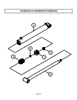
Page 18: ...HYDRAULIC CYLINDER PARTS DIAGRAM Page 16 3 5 4 1 6 2...

Page 19: ...not to scratch sealing surfaces of aluminum piston If a sharp knife is not available An electric soldering gun or hot iron may be used to melt throughout seals All gland seals shown with a sec on remo...

Page 20: ...AND CUSTOMER S REMEDIES To the extent permitted by law neither Koyker the Dealer nor any person or company affiliated with either of them makes any warranties representations conditions or promises ex...

Page 21: ...925 675 1150 850 M27 950 700 1200 875 1350 1000 1700 1250 M30 1300 950 1650 1200 1850 1350 2300 1700 M33 1750 1300 2200 1650 2500 1850 3150 2350 M36 2250 1650 2850 2100 3200 2350 4050 3000 SAE Recomme...

Reviews: