11
INSTRUCTIONS FOR THE INSTALLER
If there are other fuel burning appliances in the
same room BS 5440: Part 2:1989 should be
consulted to determine the air vent requirements.
Gas connection
Choose fixed connections or use a flexible pipe in
stainless steel in compliance with the regulation in
force. If you use flexible metallic pipes, be careful
they do not come in touch with mobile parts or they
are not squeezed. Also be careful when the hob is
put together with an oven.
ATTENTION: Make sure that the gas supply
pressure of the appliance obeys the recomend-
ed values
If the supplied pressure has not the specified
value, it is necessary to assemble a proper
pressure regulator in compliance with the standard
UNI EN 88.
For Liquid Gas (LPG) the use of pressure regulator
is allowed only if they are in compliance with UNI
EN 12864. The adjustable connection is fixed to
the comprehensive ramp by means of a threaded
nut G 1/2". Screw the parts without force, adjust
the connection inthe necessary direction and
tighten everything (fig.7).
Rigid connection
Carry out connection by using metal rigid pipes
(copper with mechanical end) (UNI-CIG 7129).
Flexible connection
Use a flexible pipe in stainless steel (UNI-CIG 9891)
with a maximum length 2m.
When installation is complete, make sure that the
seal of each pipe fittingis correct.
Use a soapy solution, not a flame
Electric connection
The connection to the electric grid must be carried
out by qualified personnel and in conformity with
the regulations in force.
The voltage of the electric system must correspond
to the value indicated in the label under the
appliance. Make sure that the electric system is
provided with an effective ground connction in
compliance with the regulations and provisions of
the law.
Grounding is compulsory
.
GAS TRANSFORMATIONS AND ADJUSTMENTS
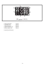
Replacing the nozzles
If the equipment is adjusted for a type of gas that is
different from the one available, it is necessary to
replace the burner nozzles.
The choice of the nozzles to replace must be
made according to the table of the “technical
characteristics” as enclosed.
Act as follows:
-Remove the racks and burners.
-By means of a straight spanner L, unscrew
the nozzle U (fig.8) and substitute it with the
corresponding one.
-Tighten the nozzle strongly.
Adjusting the burners
The lowest flame point must always be properly
adjusted and the flame must remain on even if
there is an abrupt shift from the maximum to the
minimum position.
If this is not so, it is necessary to adjust the lowest
flame point as follows:
-start the burner up
-turn the tap up to the minimum position (small
flame)
-remove the knob from the tap rod
-introduce a flat-tip screwdriver in the hole F of the
tap (fig.9-9/A-9/B) and turn the by-pass screw up
to a proper adjustment of the lowest flame point.
As regards G30 gas burners, the by-pass screw
must be tightened completely.
MAINTENANCE
Replacing the power supply cable
If the power supply cable should be replaced,
it is necessary to use a cable with a section of
3x0.75mm
2
type H05V2V2-F or H05RR-F for
models all gas or 3x1.5mm
2
type H05V2V2-F or
H05RR-F for models mixed, complying with the
regulations in force.
The connection to the terminal board must be
effected as shown in fig. 10-10/A:
brown cable L
(phase)
blue cable N
(neutral)
green-yellow cable (ground)
If the supply cord is damaged, it must be replaced
by the manufacturer, its service agent or similarly
qualified persons in order to avoid a hazard.
Summary of Contents for HK 9414 GMRB
Page 1: ...HK 9414 GMX HK 9414 GMRB HK 9414 GMRN...
Page 2: ......
Page 16: ...https korting ru support 8 800 550 78 62 K rting 2 1889 3 1 2 3 4 5 6 K rting...
Page 18: ......
Page 19: ......


