background image

 - 7 -

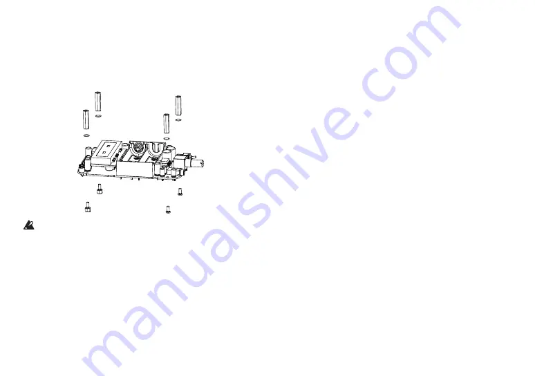
Attaching the hex spacers

1.  Mount the hex spacers (5, 6) onto the circuit board.

Use the screws (8) to affix the two hex spacers (6) and the internal 
tooth lock washers (7) for the volume and jack side. In the same way, 
tighten the hex spacers (6) on the Nutube circuit board side and the 
internal tooth lock washers (7) by tightening the screws for the lower 
hex spacers (5). 

(6)

(7)

(7)

(6)

(8)

(5)

  Since the screws (8) cannot be retightened from the outside of the 

case, use a precision screwdriver (Phillips #1) to firmly tighten the 
screws.

Summary of Contents for Nu:Tekt HA-S

Page 1: ...ssembly 6 Preparing the main circuit board and Nutube circuit board 6 Install the main circuit board into the case 8 Part Names and Functions 11 How to Use the Nu Tekt HA S 11 Adjusting the main circu...

Page 2: ...d resistance value can be adjusted letting you enjoy different sounds by changing the steepness of the load curve for the vacuum tube This unit is shaped like a mint can case which is familiar to fans...

Page 3: ...ry or package you must dispose of it in the correct manner to avoid harm to human health or damage to the environment Contact your local administra tive body for details on the correct disposal method...

Page 4: ...4...

Page 5: ...ete the assembly procedure and prepare work mats so parts will not be scratched Avoid losing the screws and nuts Handle the screws and nuts with caution to avoid losing them Do not use other screws or...

Page 6: ...ch the cushion onto the Nutube circuit board unit Attach cushion N1 2 onto the edge of the Nutube circuit board Attach cushion N2 3 onto both upper edges of the Nutube CushionN2 3 CushionN1 2 CushionN...

Page 7: ...washers 7 for the volume and jack side In the same way tighten the hex spacers 6 on the Nutube circuit board side and the internal tooth lock washers 7 by tightening the screws for the lower hex spac...

Page 8: ...reatment 1 4 Knurled screw M2 L 6mm 4 5 Main circuit board Parts for assembly on pages 6 and 7 1 6 Insulation sheet PET 1 7 Volume nut Included with Volume 1 8 Volume washer Included with Volume 1 9 V...

Page 9: ...d nut remove the washer and nut and then mount the main circuit board onto the case 3 Attach the washer 8 to the volume and then use the volume nut 7 to temporarily tighten the volume onto the case Ma...

Page 10: ...e back side attach the battery cushion in the position shown in the diagram below 3 With the printed jack names facing the jack side put the cover 3 on and fasten the knurled screws 4 in four places T...

Page 11: ...els between left and right The tonal character will also change when adjusting the sound Adjust the settings to get the sound you like 1 5 4 2 3 1 NFB switch Setting the switch to A will set the circu...

Page 12: ...cuit is not equipped in pursuit of the superior sound Connect a pair of headphones or the like to the jack after you turn on the power Replacing the operational amplifier The operational amplifier can...

Page 13: ...13 Mounting Diagram...

Page 14: ...itor 220 F 25V 2 11 C24 Electrolytic capacitor 220 F 6 3V 1 12 C18 Electrolytic capacitor OPEN 13 R16 Chip resistor 0 1 14 R29 R30 Chip resistor 10 1 4W 2 15 R32 Chip resistor 1K 1 Part number Circuit...

Page 15: ...4 7 F B 1 38 C7 Chip ceramic capacitor 4 7 F B 1 39 C1 C2 Chip ceramic capacitor 22 F B 2 40 C25 Chip Electrolytic capacitor 390 F 2 5V 1 41 C29 C30 C31 C32 Chip ceramic capacitor 10 F B 4 42 R33 Chip...

Page 16: ...1 3 4 3 BATT1 BATTERY BOX R9 22K R8 22K 5 4 6 SW1B 2UD1 T1 GND GND GND R21 10K C10 10PF CH C26 100uF 35V R32 1K VCC_2 VCC_2 2 1 3 SW2A MK 22D10 G2 5 4 6 SW2B MK 22D10 G2 R17 47K R18 47K C16 0 012uF F...

Reviews: