Appendix B
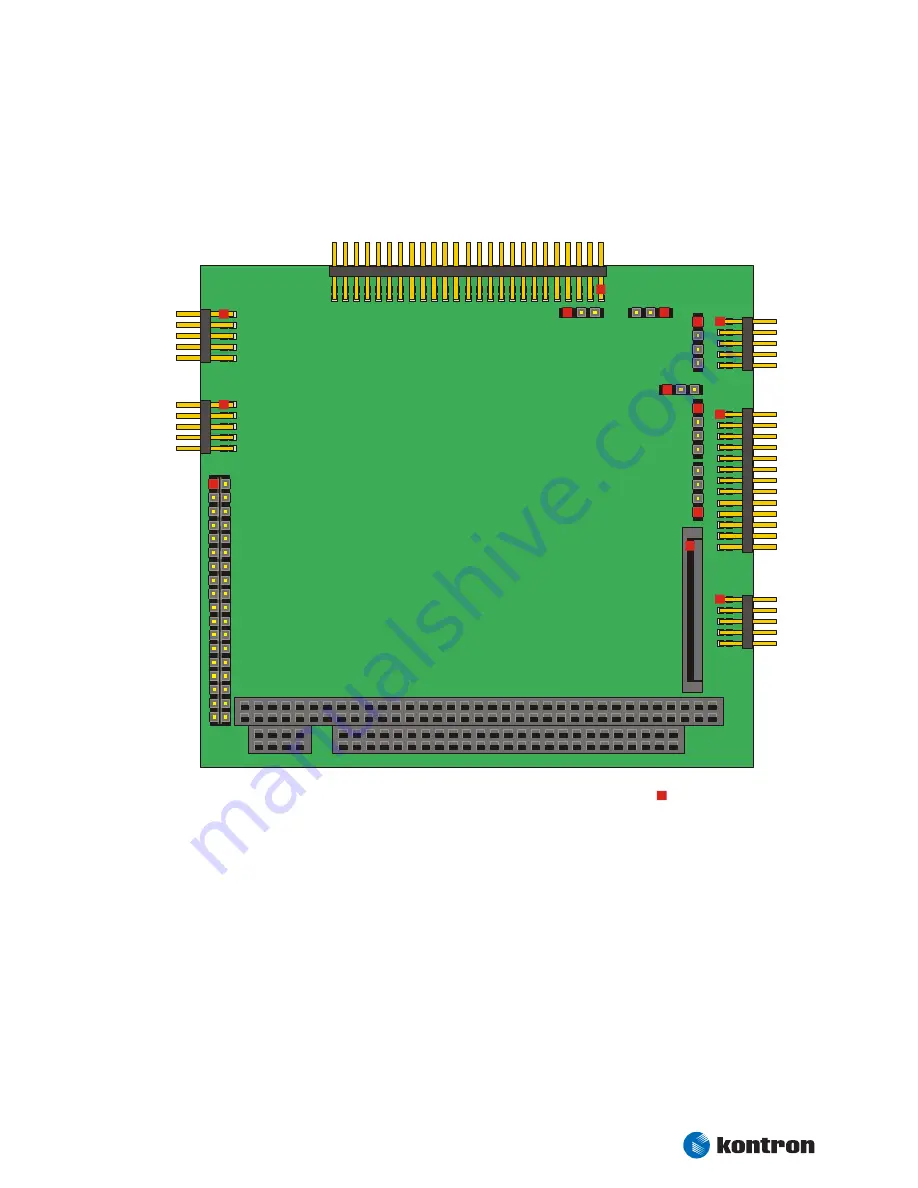
Connector Layout
Kontron User's Guide PC/104-520
48
Appendix B: Connector Layout
Pin 1
J4
J2
J13
J9
J8
J1
J3
J17
J16
J7
J22
J12
J10
J11
P6
The Board as depicted is a model only, showing the positions of the connectors. For pincount and pinning
please see the following tables.