GPIO Level Configuration
Feature
Option Description
GPO0 Level GPO1 Level
GPO2 Level GPO3 Level
Low
High
Configure initial level of GPOs
78
Page 1: ...microETXexpress DC Document Revision 1 14 If it s embedded it s Kontron...
Page 2: ......
Page 3: ...fication 10 3 1 Modules Accessories 10 3 2 Functional Specification 11 3 3 Block Diagram 16 3 4 Electrical Specification 17 3 4 1 Supply Voltage 17 3 4 2 Power Supply Rise Time 17 3 4 3 Supply Voltage...
Page 4: ...rdware Monitor 32 4 10 5 SIO Winbond 83627DHGP 32 4 10 6 SIO Winbond 83627HG 33 4 11 GPIO General Purpose Input and Output 34 4 12 Dual Staged Watchdog Timer 35 4 13 Flash Backup Feature 36 4 14 Speed...
Page 5: ...B 49 6 2 4 Connector X1B Row C 51 6 2 5 Connector X1B Row D 53 7 BIOS Operation 55 7 1 Determining the BIOS Version 55 7 2 Setup Guide 55 7 2 1 Start AMI BIOS Setup Utility 55 7 3 BIOS Setup 57 7 3 1...
Page 6: ...stored in a retrieval system or translated into any language or computer language in any form or by any means electronic mechanical photocopying recording or otherwise without the express written perm...
Page 7: ...r maintenance Kontron Embedded Modules GmbH will not be responsible for any defects or damages to other products not supplied by Kontron Embedded Modules GmbH that are caused by a faulty Kontron Embed...
Page 8: ...ble host computer packaged as a super component Interfaces will provide a smooth transition path from legacy parallel interfaces to LVDS Low Voltage Differential Signaling interfaces These include the...
Page 9: ...fication This standardization allows designers to create a single system baseboard that can accept present and future COM Express modules COM Express modules include common personal computer PC periph...
Page 10: ...e DC N270 4GB SSD E1 Intel Atom N270 DDR2 945GSE 4GB onboard SSD Accessories Product Number Product Name 38102 0000 00 1 COM Express miniBaseboard Type 2 38104 0000 00 0 COM Express Eval Type 2 97011...
Page 11: ...gies Idle States C States Execute Disable Bit CPU specifications Intel ATOM Codename Diamondville L2 Cache 512kB FSB 533MHz Instruction set 32bit Memory Sockets 1 x DDR2 SO DIMM Memory Type DDR2 400 5...
Page 12: ...Model 2 0 Hardware accelerated Video Independent Simultaneous Displays 2 Display Port HDCP support SDVO available via ADD2 DDI1 Monitor output CRT max Resolution QXGA 2048x1536 TV out YES LVDS LVDS Bi...
Page 13: ...2 4 0 CE 2 4 1 and newer Flash Size 4GB industrial 4GB industrial Flash Part No SST85LD1004T 60 RI Greenliant GLS85LP1004P S I FTE NAND Type SLC NAND SLC NAND Host write Cycles 100M 70M Flash Erase Cy...
Page 14: ...M 1 2 SLB9635TT Miscellaneous Kontron Features External I2C Bus Fast I2C MultiMaster capable M A R S support YES Embedded API JIDA16 JIDA32 PICMG EAPI JIDA32 Applications K Station YES Custom BIOS Set...
Page 15: ...The microETXexpress DC currently supports Microsoft Windows CE 6 0 Microsoft Windows XP embedded Microsoft Windows XP x86 Microsoft Windows 7 x86 Microsoft Windows Embedded Standard 7 x86 WES7 Linux W...
Page 16: ...3 3 Block Diagram 16...
Page 17: ...Rise Time The input voltages shall rise from 10 of nominal to within the regulation ranges within 0 1ms to 20ms There must be a smooth and continuous ramp of each DC input voltage from 10 to 90 of it...
Page 18: ...Modules GmbH heatspreader plate assembly The operating temperature defines two requirements the maximum ambient temperature with ambient being the air surrounding the module the maximum measurable te...
Page 19: ...gnition UL 60950 1 The COM Express compact form factor Computer on Modules are Recognized by Underwriters Laboratories Inc Representative samples of this component have been evaluated by UL and meet a...
Page 20: ...ing to IEC EN 60068 2 6 Non operating Vibration sinusoidal 10Hz 4000Hz 0 15mm 2g IEC EN 60068 2 27 Non operating Shock Test half sinusoidal 11ms 15g EMC Validated in Kontron reference housing for EMC...
Page 21: ...to have not been burned in Other environmental stresses extreme altitude vibration salt water exposure etc lower MTBF values System MTBF hours 199784 40 C Fans usually shipped with Kontron Embedded M...
Page 22: ...3 8 Mechanical Specification Dimension 95 0 mm x 95 0 mm 3 75 x 3 75 Hight approx 12mm 0 4 CAD drawings are available at EMD CustomerSection 22...
Page 23: ...rside of the heatspreader assembly implement thermal interfaces between the heatspreader plate and the major heat generating components on the microETXexpress DC About 80 percent of the power dissipat...
Page 24: ...nector The onboard fan connector J9 can be found at the left side nearby the DRAM socket and has following specification Part number Molex J9 53261 0390 Mates with 51021 0300 Crimp terminals 50079 810...
Page 25: ...ed PWM value 0 255 can be entered to run the fan at a selected speed The used hardware monitor onboard is an ADT7475 For additional information please refer to the regarding datasheet 3 11 1 Electrica...
Page 26: ...lly up to 300mA just to stay off This mode allows to be switched on by power button RTC event and WakeOnLan even when it is not necessary The new S5 Eco mode reduces the current tremendously The S5 Ec...
Page 27: ...ow level Power Button Event Pressing the power button for at least 4seconds will turn off power to the module Power Button Override Power Good PWR_OK The microETXexpress DC provides an external input...
Page 28: ...Express Design Guide maintained by PICMG Please refer to the official PICMG documentation for additional information The LPC bus does not support DMA Direct Memory Access This leads to limitations for...
Page 29: ...DA16 and JIDA32 4 6 K Station 1 Based on the JIDA32 interface users can implement advanced board functionalities in their application As an example utility Kontron provides K Station for most 32bit Wi...
Page 30: ...ontrol only no PWM support 4 8 K Station 2 Based on the JIDA32 interface users can implement advanced board functionalities in their application As an example utility Kontron provides K Station for mo...
Page 31: ...e ADT7475 Temp 2 chipset temperature Northbridge Temp 3 external carrier board SIO Winbond 83627 Temp Sensor 0 Temp 3 external carrier board SIO Winbond 83627 Temp Sensor 1 Temp 5 external carrier boa...
Page 32: ...nboard Hardware Monitor Sensor Function Temp 0 CPU Temperature measured with ADT7475 HWM Temp 1 Board Temperature internal IC temperature of onboard ADT7475 HWM Temp 2 Chipset Temperature FAN 0 Onboar...
Page 33: ...Voltage 3 Voltage Sensor 1 VCoreB Voltage 4 Voltage Sensor 2 3 3V VIN Voltage 5 Voltage Sensor 3 5V AVCC Voltage 6 Voltage Sensor 4 12V VIN Voltage 7 Voltage Sensor 5 12V VIN Voltage 8 Voltage Sensor...
Page 34: ...neral Purpose Input 0 GPI1 A63 General Purpose Input 1 GPI2 A67 General Purpose Input 2 GPI3 A85 General Purpose Input 3 GPO0 A93 General Purpose Output 0 GPO1 B54 General Purpose Output 1 GPO2 B57 Ge...
Page 35: ...et A reset will restart the module and starts POST and operating system new NMI A non maskable interrupt NMI is a computer processor interrupt that cannot be ignored by standard interrupt masking tech...
Page 36: ...Flash Backup This new feature allows saving custom defaults directly into the Flash With invalid EEPROM data or without a CMOS EEPROM the module will start up with these custom defaults It s possible...
Page 37: ...s Customer Section Extract the BIOS including custom defaults with afudos or kflash utility for windows Tool Command AFUDOS c afudos exe biosname rom O KFLASH c kflash exe backup biosname rom Flash yo...
Page 38: ...drops to lower frequencies by changing the CPU ratios and voltage conserving battery life while maintaining a high level of performance The frequency is set back automatically to the high frequency a...
Page 39: ...C2 additionally reduces CPU voltage C3 Deep Sleep Stops all CPU internal and external clocks C3E Extended Stop Grant Similar to C3 additionally reduces CPU voltage C4 Deeper Sleep Reduces CPU voltage...
Page 40: ...y duplicating certain sections of the processor those that store the architectural state but not duplicating the main execution resources This allows a Hyper Threading equipped processor to pretend to...
Page 41: ...ows Vista Windows 7 The following events resume the system from S3 USB Keyboard 1 USB Mouse 1 Power Button WakeOnLan 2 The following events resume the system from S4 Power Button WakeOnLan 2 The follo...
Page 42: ...ailable in Advanced Configuration and Power Interface ACPI mode Used as System Control Interrupt SCI in ACPI mode Currently not free in Non ACPI mode 5 1 2 In APIC mode IRQ Used For Available Comment...
Page 43: ...for device is disabled in setup the corresponding DMA channel is avaialble for other devices 3 LPT No Unavailable if LPT is used in ECP mode 4 Cascade No 5 No 6 No 7 No 5 3 Memory Area Upper Memory U...
Page 44: ...5 7 JILI I2C Bus I2C Address Used For Available Comment JIDA Bus Nr A0h DDC No EEPROM for JILI Data 3 62h MAX5362 No DAC for Backlight brightness 3 JIDA Bus Nr 0 is for internal use only 44...
Page 45: ...inouts for Interface Connectors X1A and X1B are documented for convenient reference Please see the COM Express Specification and COM Express Design Guide for detailed design level information 6 1 Conn...
Page 46: ...log OD Output Open Drain O 1 8 1 8V Output O 3 3 3 3V Output O 5 5V Output DP I O Differential Pair Input Output DP I Differential Pair Input DP O Differential Pair Output PU Pull Up Resistor PD Pull...
Page 47: ...2 AC_BITCLK HDA_BITCLK HD Audio Clock O 3 3 int PD 20k in ICH7 A33 AC_SDOUT HDA_SDOUT HD Audio Data O 3 3 int PD 20k in ICH7 A34 BIOS_DISABLE BIOS_DISABLE I 3 3 PU 10k 3 3V S0 A35 THRMTRIP EXT_THRMTRI...
Page 48: ..._DDC_CLK JILI I2C Clock I O 3 3 PU 2k21 3 3V s0 A84 LVDS_I2C_DAT LVDS_DDC_DATA JILI I2C Data I O 3 3 PU 2k21 3 3V s0 A85 GPI3 EXT_GPI3 General Purpose Input 3 I 3 3 PU 10k 3 3V S0 A86 KBD_RST KBD_RST...
Page 49: ...Data 0 I 3 3 PD 20k in ICH7 B31 GND Power Ground PWR B32 SPKR HDA_SPKR Speaker O 3 3 PD 20k in ICH7 B33 I2C_CK I2C_CLK_EXT I2C clock O 3 3 PU 2k21 3 3V S0 B34 I2C_DAT I2C_DATA_EXT I2C data I O 3 3 PU...
Page 50: ...Y_ETX 5V Standby PWR 5V S5 B86 VCC_5V_SBY V_STBY_ETX 5V Standby PWR 5V S5 B87 VCC_5V_SBY V_STBY_ETX 5V Standby PWR 5V S5 B88 RSVD n c nc B89 VGA_RED CRT_RED Analog Video RGB RED OA PD 150R B90 GND Pow...
Page 51: ...PCI_AD12 PCI Adress Data Bus line I O 5T C31 GND Power Ground PWR C32 PCI_AD14 PCI Adress Data Bus line I O 5T C33 PCI_C BE1 PCI Bus Cmd Byte enables 1 I O 5T C34 PCI_PERR PCI Bus Grant Error I O 5T...
Page 52: ...6 PEG_RX10 n c nc C87 GND Power Ground PWR C88 PEG_RX11 n c nc C89 PEG_RX11 n c nc C90 GND Power Ground PWR C91 PEG_RX12 n c nc C92 PEG_RX12 n c nc C93 GND Power Ground PWR C94 PEG_RX13 n c nc C95 PEG...
Page 53: ...D13 PCI Adress Data Bus line I O 5T D30 PCI_AD15 PCI Adress Data Bus line I O 5T D31 GND Power Ground PWR D32 PCI_PAR PCI Bus Parity I O 5T D33 PCI_SERR PCI Bus System Error I O 5T PU 8k2 3 3V S0 D34...
Page 54: ...EG_TX11 n c nc D90 GND Power Ground PWR D91 PEG_TX12 n c nc D92 PEG_TX12 n c nc D93 GND Power Ground PWR D94 PEG_TX13 n c nc D95 PEG_TX13 n c nc D96 GND Power Ground PWR D97 PEG_ENABLE n c nc PU 10k 3...
Page 55: ...changes system behavior by modifying the BIOS configuration The setup program uses a number of menus to make changes and turn features on or off Functional keystrokes in POST Key Function DEL Enter S...
Page 56: ...this menu F10 Save and exit Enter Execute command or select submenu Alt R Refresh screen Selecting an Item Use the or key to move the cursor to the field you want Then use the and keys to select a va...
Page 57: ...7 3 BIOS Setup 7 3 1 Main Menu Feature Option Description System Time hh mm ss Tab Shift Tab or Enter selects field System Date mm dd yyyy Tab Shift Tab or Enter selects field 7 3 2 Module Info 57...
Page 58: ...Module Component Steppings Module Software Revisions 58...
Page 59: ...Current LVDS Configuration 59...
Page 60: ...7 3 3 Advanced Menu 60...
Page 61: ...ure DTS based Thermal Management Enabled Disabled Enable Disable Thermal Management utilizing the CPU s Digital Thermal Sensor SpeedStep Enabled Disabled Enables and Disables the SpeedStep power manag...
Page 62: ...E AHCI Selects the SATA mode in Enhanced IDE mode Configure SATA Channels Before PATA Behind PATA Configure when the SATA controller is initialized in Enhanced IDE mode Hard Disk Write Protect Disable...
Page 63: ...vice occurs one sector ata atime Auto The data transfer from and to the device occurs multiple sectors at a time if the device supports ist PIO Mode Auto 0 1 2 3 4 Auto Configures the PIO Mode DMA Mod...
Page 64: ...dress Disabled 3F8 IRQ4 2F8 IRQ 3 3E8 IRQ4 2E8 IRQ3 Selects the Address of COM Port 2 Serial Port2 Mode Normal IrDA ASK IR Parallel Port Address Disabled 378 278 3BC Selects the Address of the LPT Por...
Page 65: ...I USB Device Wakeup From S3 S4 Disabled Enabled Enables Disables the possibility to wake up via USB from S3 and S4 High Performance Event Timer Disabled Enabled Enables Disables the High Performance E...
Page 66: ...ssive TC2 value 1 2 5 16 This value sets the TC2 value for the ACPI Passive Cooling Formula Only visible when Passive Trip Point is enabled Passive TSP value 2 4 10 30 This item sets the TSP value for...
Page 67: ...delta Tt is the target temperature passive cooling trip point The two coefficients TC1 and TC2 and the sampling period TSP are hardware dependent constants the end user must supply It s up to the end...
Page 68: ...nd L1 link power states PCIE Port N Auto Enabled Disabled Enables Disables or autoconfigures the PCIE Port N PCIE High Priority Port Disabled Port 0 Port 1 Port 2 Port 5 Select the PCIE Port that gets...
Page 69: ...Enabled Enables IO port 60h 64h emuluation support USB 2 0 Controller Mode FullSpeed HiSpeed Configures the USB 2 0 controller in HiSpeed 480Mbps or FullSpeed 12Mbps BIOS EHCI Hand Off Disabled Enable...
Page 70: ...ber of seconds POST waits for the USB mass storage device after start unit command Emulation Type Auto Floppy Forced FDD Hard Disk CDROM If Auto USB devices with less than 530MB will be emulated as fl...
Page 71: ...g Device PWM 1 Mode Setting Auto Fan Mode Fan Always On Full Fan Disable Mode Fan Manually Mode PWM Configuration Mode Setting PWM 1 Ramp Rate Time Slot 1 Time Slot 2 Time Slot 3 Time Slot 4 Time Slot...
Page 72: ...n Speed Devisor 1 1 2 4 128 Sets the register setting for the baseboard windbond fan speed devisor for fan 1 Fan Speed Devisor 2 1 2 4 128 Sets the register setting for the baseboard windbond fan spee...
Page 73: ...ard Crisis Recovery Disabled Enabled Enables Disables Keyboard Crisis Recovery function by USB keyboard External I2C Bus Speed 800Khz 400Khz 200Khz 1Khz Selects the Speed of the I2C bus interface S5 E...
Page 74: ...MARS Interface Configuration Feature Option Description MARS Disabled Auto SMB Charger SMB Manager Enables the MARS function 74...
Page 75: ...ime to wait once during boot up Cascade without action used every retrigger Assert WDT Disabled Enabled Enable disable assertion of WDT signal to baseboard on stage timeout Stage 1 Timeout 0 4s 1s 5s...
Page 76: ...edirection Flow Control none Hardware Software Selects the flow control for serial connection Redirection After BIOS POST Always Disabled Bootloader Always Redirection is always active Disabled Turns...
Page 77: ...LAN Controller Feature Option Description Ethernet Controller Disabled Enabled Disables Enables the onboard Ethernet interface Ethernet Boot Disabled Enabled Disables Enables the PXE Boot ROM 77...
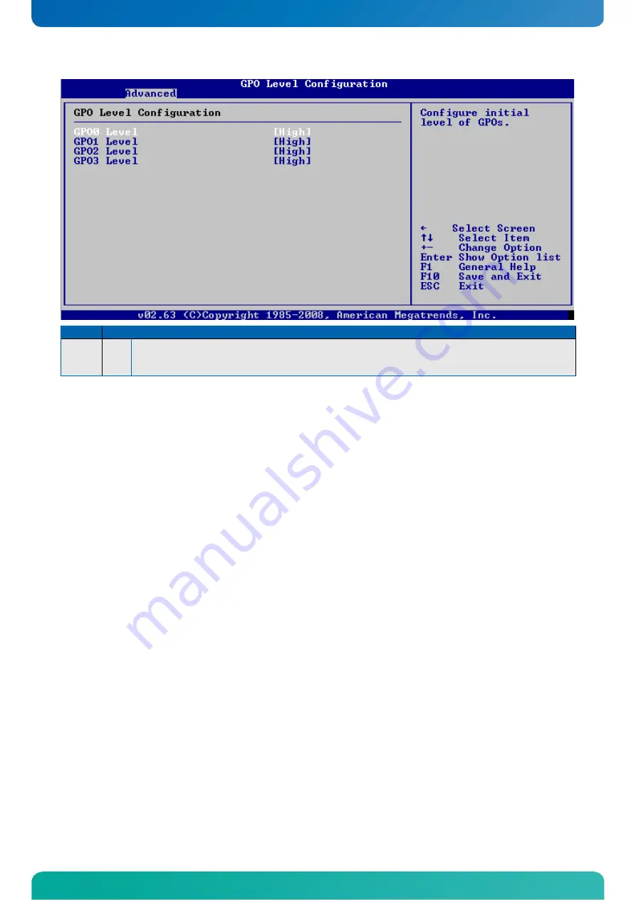
Page 78: ...GPIO Level Configuration Feature Option Description GPO0 Level GPO1 Level GPO2 Level GPO3 Level Low High Configure initial level of GPOs 78...
Page 79: ...Trusted Computing Feature Option Description TCG TPM Support Yes No Enables Disables Trusted Computing and Trusted Platform Module 79...
Page 80: ...y register Allocate IRQ to PCI VGA Yes No Decided if PCI VGA card does get an IRQ assigned if requested PCI IDE BusMaster Disabled Enabled Disables and enables PCI IDE Busmaster OffBoard PCI ISA IDE C...
Page 81: ...tion ROM Bootup Num Lock On Off Select Power On state for Num Lock PS 2 Mouse Support Auto Disabled Enabled Disables and enables or auto selects PS 2 Mouse Support Wait For F1 If Error Disabled Enable...
Page 82: ...3 6 Security Feature Option Description Change Supervisor Password Type in Change User Password Type in Boot Sector Virus Protection Disabled Enabled Enables or disables boot sector virus protection 8...
Page 83: ...phics adapter is initialized during boot up and gets priority Internal Graphics Mode Select Disabled Enabled 1MB Enabled 8MB Select the mode for the interal graphicdevice Chipset Thermal Throttling Di...
Page 84: ...LVDS CRT LVDS Selects the Boot Display Devices TV Connector Auto Composite Component Composite RGB S Video SCART Composite SCART Compos RGB SCART Compos S Video SMPTE253 Compon RGB Selects the TV Con...
Page 85: ...Single Channel Dual Channel Selects if 1x or 2x LVDS signals are used only in FPM Fixed Mode Color Depth 18bit Selects the Color Depth of the connected LVDS display only in FPM Fixed Mode Dithering E...
Page 86: ...orts USB 2 0 Controller Enabled Disabled Enables Disables the USB 2 0 controller Audio Controller Auto Azalia AC 97 Audio und Modem All Disable Selects the mode for Audio Controller SMBUS Controller E...
Page 87: ...ize of the decode range in kB LPC Decode Range 2 Base 0 FFFF Enter the Base Adress of the LPC decode range LPC Decode Range 2 Size Disabled 4 8 256 Size of the decode range in kB LPC Decode Range 4Eh...
Page 88: ...49 0 8165 77 777 Fax 49 0 8165 77 219 info kontron com North America 14118 Stowe Drive Poway CA 92064 7147 USA Tel 1 888 294 4558 Fax 1 858 677 0898 info us kontron com Asia Pacific 17 Building Block...