KTD-00781-A
KTG41 family
Page 13 of 78
www.kontron.com
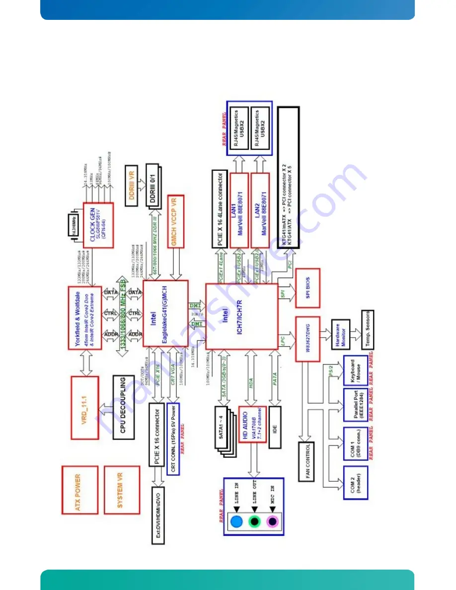
2.2 System
overview
The block diagram below shows the architecture and main components of the KTG41 board. The two key components on the board are the Intel
®
G41 and Intel
ICH7R Chipsets.
Page 1: ...If it s embedded it s Kontron KTG41 Users Guide KTD 00781 A KTG41 ATXu...
Page 2: ...S reserves the right to make changes without notice to any product including circuits and or software described or contained in this manual in order to improve design and or performance Specifications...
Page 3: ...xpected to cause the failure of the life support device or system or to affect its safety or effectiveness KONTRON Technology Technical Support and Services If you have questions about installing or u...
Page 4: ...6 Power Consumption 19 3 Connector Definitions 21 3 1 Connector layout 22 3 1 1 KTG41 Top Side View 22 3 1 2 KTG41 IO Bracket area 22 3 2 Power Connector ATX BTXPWR 23 3 3 Keyboard and Mouse connecto...
Page 5: ...DROM Audio Input CDROM 39 3 12 3 Audio Header AUDIO_HEAD 40 3 13 Fan Connector FAN_CPU 41 3 14 Clear CMOS Jumper Clr CMOS JBAT1 42 3 15 The SPI Jumper SPI Jumper JP6 42 3 16 TPM Connector TPM 43 3 17...
Page 6: ...6 6 Advanced settings Voltage Monitor 63 6 6 7 Advanced settings ACPI Settings 64 Advanced settings Trusted Support 65 6 6 8 Advanced settings USB Configuration 66 6 6 9 Advanced settings USB Mass Sto...
Page 7: ...ntel Yorkfield and Wolfdale families Use of this Users Guide implies a basic knowledge of PC AT hard and software This manual is focused on describing the KTG41 special features and is not intended to...
Page 8: ...thumb while opening closing the load lever otherwise lever can bounce back like a mouse trap and WILL cause bent contacts when loaded 1 Disengage Load Lever by depressing down and out on the hook to...
Page 9: ...paste or adhesive pads between CPU and cooler and connect the Fan electrically to the FAN_CPU connector 5 Connecting Interfaces Insert all external cables for hard disk keyboard etc A CRT monitor must...
Page 10: ...ilbage til leverand ren ADVARSEL Eksplosjonsfare ved feilaktig skifte av batteri Benytt samme batteritype eller en tilsvarende type anbefalt av apparatfabrikanten Brukte batterier kasseres i henhold t...
Page 11: ...y port and DVI support The digital ports are multiplexed on to the PEG interface using passive PEG card Accessory Serial Digital Video Out SDVO ports 2 channels for additional CRT LVDS panel DVI TV Ou...
Page 12: ...lity to provide sufficient airflow around each of the components to keep them within allowed temperature range Storage 20 C 70 C and 5 95 relative humidity non condensing Electro Static Discharge ESD...
Page 13: ...mily Page 13 of 78 www kontron com 2 2 System overview The block diagram below shows the architecture and main components of the KTG41 board The two key components on the board are the Intel G41 and I...
Page 14: ...5 6 Yes 2 66 1333 Q9400S 65 6 2 50 1333 Q9300 95 6 2 66 1333 Q8400 95 4 2 66 1333 Q8400S 65 4 2 50 1333 Q8300 95 4 2 33 1333 Q8200 95 4 2 33 1333 Q8200S 65 4 Intel Core 2 Duo 3 33 1333 E8600 65 6 Wolf...
Page 15: ...tium 2 Cores 2 70 800 E5400 65 2 Conroe 2 60 800 E5300 65 2 Yes 2 50 800 E5200 65 2 2 40 800 E2220 65 1 2 20 800 E2200 65 1 2 00 800 E2180 65 1 1 80 800 E2160 SLA8Z 65 1 Yes 1 60 800 E2140 65 1 Intel...
Page 16: ...800 memory is used with a 800 MHz system bus frequency processor the memory clock will operate at 400 MHz The table below lists the resulting operating memory frequencies based on the combination of...
Page 17: ...digital CRT HDTV at 1400x1050 85 Hz o Dual independent display options with digital display o Multiplexed digital display channels supported with ADD2 Card o Supports TMDS transmitters or TV Out encod...
Page 18: ...an either be configured to support simultaneous display with the primary VGA display or can be configured to support dual independent display as an extended desktop configuration with different colour...
Page 19: ...tandard 12V 11 4V 12 6V Should be 5 for compliance with the ATX specification 12V 13 2V 10 8V Should be 10 for compliance with the ATX specification 5V 5 50V 4 5V Not required for the KTQ45 boards 5VS...
Page 20: ...49A 17 45W 3V3 0 24A 0 79W 12V 0 00A 0W 5VSB 0 00A 0W Total 56 76W S1 Mode Mean No external load Supply Current draw Power consumption 12V 1 14A 13 68W 5V 0 15A 0 75W 3V3 2 02A 6 66W 12V 0 00A 0W 5VS...
Page 21: ...te IO pin IS Schmitt trigger input TTL compatible IOC Input open collector Output TTL compatible NC Pin not connected O Output TTL compatible OC Output open collector or open drain TTL compatible OT O...
Page 22: ...e x4 ATX BTXPWR SPI PCI Slot 2 PCIe x16 SDVO LPT FAN_SYS KBDMSE FRONTPNL AUDIO_HEAD FEATURE Ext TPM FAN_CPU PCI Slot 1 ATX 12V 4pin USB0 USB1 CPU Socket COM2 JP5 JP4 JBAT1 JP6 SPI jumper JP5 JP4 used...
Page 23: ...12V 1 3 GND PWR 1 PWR 12V 2 4 GND PWR Note 1 Use of the 4 pin ATX 12V Power Connector is required for operation of the KTG41 Signal Description P_OK P_OK is a power good signal and should be asserted...
Page 24: ...BD 2K7 PWR 5V SB5V 4 3 GND PWR NC 2 1 MSDAT IOC TBD 2K7 NC 6 5 KBDCLK IOC TBD 2K7 PWR 5V SB5V 4 3 GND PWR NC 2 1 KBDDAT IOC TBD 2K7 Signal Description Keyboard and mouse Connector MSE KBD see below 3...
Page 25: ...SYNC O TBD 9 5V PWR 1 NC 4 14 VSYNC O TBD 10 GND PWR PWR GND 5 15 DDCCLK IO TBD 2K2 Signal Description CRT Connector Pin Signal Description 1 RED Analogue output carrying the red colour signal to the...
Page 26: ...2V B1 A1 NC 12V B2 A2 12V 12V B3 A3 12V GND B4 A4 GND SMB_CLK B5 A5 NC SMB_DATA B6 A6 NC GND B7 A7 NC 3V3 B8 A8 NC NC B9 A9 3V3 SB3V3 B10 A10 3V3 WAKE B11 A11 RST NC B12 A12 GND GND B13 A13 PCIE_x16 C...
Page 27: ...6 B54 A54 GND PEG_TXN 6 B55 A55 GND GND B56 A56 PEG_RXP 6 GND B57 A57 PEG_RXN 6 PEG_TXP 5 B58 A58 GND PEG_TXN 5 B59 A59 GND GND B60 A60 PEG_RXP 5 GND B61 A61 PEG_RXN 5 PEG_TXP 4 B62 A62 GND PEG_TXN 4...
Page 28: ...XN 2 B20 A20 GND GND B21 A21 PCIE_RXP 2 GND B22 A22 PCIE_RXN 2 PCIE_TXP 3 B23 A23 GND PCIE_TXN 3 B24 A24 GND GND B25 A25 PCIE_RXP 3 GND B26 A26 PCIE_RXN 3 PCIE_TXP 4 B27 A27 GND PCIE_TXN 4 B28 A28 GND...
Page 29: ...NC B63 A63 GND GND B64 A64 NC GND B65 A65 NC NC B66 A66 GND NC B67 A67 GND GND B68 A68 NC GND B69 A69 NC NC B70 A70 GND NC B71 A71 GND GND B72 A72 NC GND B73 A73 NC NC B74 A74 GND NC B75 A75 GND GND...
Page 30: ...D O DAA1 33 34 CBLIDA I TBD O DAA0 35 36 DAA2 O TBD TBD O HDCSA0 37 38 HDCSA1 O TBD I HDACTA 39 40 GND PWR Signal Description DAA2 0 Address lines used to address the I O registers in the IDE hard dis...
Page 31: ...ces are assigned IRQ 14 and 15 In Native mode standard PCI Conventional bus resource steering is used Native mode is the preferred mode for configurations using the Windows XP and Windows Vista operat...
Page 32: ...tached is as follows Signal Description PD7 0 Parallel data bus from PC board to printer The data lines are able to operate in PS 2 compatible bi directional mode SLIN Signal to select the printer sen...
Page 33: ...y indicates that the modem or data set is ready to establish a communications link RTS Request To Send indicates to the modem or data set that the on board UART is ready to exchange data CTS Clear To...
Page 34: ...Ioh Iol Type Signal PIN Signal Type Ioh Iol Pull U D Note I DCD 1 2 DSR I I RxD 3 4 RTS O O TxD 5 6 CTS I O DTR 7 8 RI I PWR GND 9 10 5V PWR 1 Note 1 The COM2 5V supply is fused with 1 1A resettable f...
Page 35: ...1 MDI 1 In MDI mode this is the second pair in 1000Base T i e the BI_DB pair and is the receive pair in 10Base T and 100Base TX In MDI crossover mode this pair acts as the BI_DA pair and is the transm...
Page 36: ...t 0 and 1 are supplied on the internal USB0 USB1 connector USB Ports 2 and 3 are supplied on the internal FRONTPNL connector please refer to the FRONTPNL connector section for the pin out Note It is r...
Page 37: ...least 5 00V Signal Description USB0 USB0 USB1 USB1 Differential pair works as Data Address Command Bus 5V SB5V 5V supply for external devices SB5V is supplied during powerdown to allow wakeup on USB...
Page 38: ...LINE1 IN R IA 1 SLEEVE GND PWR TIP FRONT OUT L OA RING FRONT OUT R OA SLEEVE GND PWR TIP MIC1 L IA 1 RING MIC1 R IA 1 SLEEVE GND PWR Note 1 Signals are shorted to GND internally in the connector when...
Page 39: ...te 1 CD_Left IA 1 2 CD_GND IA 3 CD_GND IA 4 CD_Right IA 1 Note 1 The definition of which pins are use for the Left and Right channels is not a worldwide accepted standard Some CDROM cable kits expect...
Page 40: ...NC 21 22 AAGND PWR GND 23 24 SPDIF IN SPDIF OUT 25 26 GND PWR Signal Description Note FRONT OUT L Front Speakers Speaker Out Left FRONT OUT R Front Speakers Speaker Out Right REAR OUT L Rear Speakers...
Page 41: ...from the fan for supervision The signals shall be generated by an open collector transistor or similar Onboard is a pull up resistor 4K7 to 12V The signal has to be pulsed typically twice per rotatio...
Page 42: ...wer connected to the system the battery will fully depleted within a few weeks WARNING JP4 and JP5 are used to select the BIOS to boot These jumpers are for manufacturing purpose only and they shall a...
Page 43: ...Pull U D Note SPI_CLK 1 2 SB3V3 PWR NC 3 4 BOOT0 IO 10K SPI_CS2 5 6 BOOT1 IO 10K SPI_MOSI 7 8 MFG 10K SPI_MISO 9 10 GND PWR Note Pull U D Ioh Iol Type Signal PIN Signal Type Ioh Iol Pull U D Note PWR...
Page 44: ...tials Bus Data Address Command Bus USB3 USB3 Universal Serial Bus Port 3 Differentials Bus Data Address Command Bus 5V Maximum load is 1A or 2A per pin if using IDC connector flat cable or crimp termi...
Page 45: ...no power failures are detected SB5V StandBy 5V supply SB3V3 Max load is 0 75A 1 5A 1 sec EXT_BAT EXTernal BATtery option for connecting terminal of an external primary cell battery 2 5 4 0 V terminal...
Page 46: ...IOT C BE3 F26 E26 GNT1 OT IOT AD23 F27 E27 3 3V PWR PWR GND F28 E28 AD22 IOT IOT AD21 F29 E29 AD20 IOT IOT AD19 F30 E30 GND PWR PWR 3 3V F31 E31 AD18 IOT IOT AD17 F32 E32 AD16 IOT IOT C BE2 F33 E33 3...
Page 47: ...nd valid one clock after either IRDY is asserted on a write transaction or TRDY is asserted on a read transaction Once PAR is valid it remains valid until one clock after the completion of the current...
Page 48: ...t will be catastrophic If an agent does not want a non maskable interrupt NMI to be generated a different reporting mechanism is required SERR is pure open drain and is actively driven for a single PC...
Page 49: ...ble kit COM2 Wuerth 61201020621 Molex 90635 1103 Kontron KT 821016 cable kit Kontron KT 821017 cable kit USB0 USB1 Pinrex 512 90 10GBB2 Kontron KT 821401 cable kit USB2 USB3 FRONTPNL Kontron KT 821401...
Page 50: ...gh Definition Audio FE9FF800 FE9FFBFF 1024 Intel R 82801GB ICH7 USB2 Enhanced Host Controller FE9FFC00 FE9FFFFF 1024 Intel R 82801GB ICH7 Serial ATA Storage Controller FEA00000 FEAFFFFF 1048576 Intel...
Page 51: ...29 0 8086 27C8 Intel ICH7 USB Universal Host Controller 0 29 1 8086 27C9 Intel ICH7 USB Universal Host Controller 0 29 2 8086 27CA Intel ICH7 USB Universal Host Controller 0 29 3 8086 27CB Intel ICH7...
Page 52: ...USB Universal Host Controller Intel R 82801G ICH7 PCI Express Root Port Intel R 82801GR GH GHM ICH7 PCI Express Root Port Microsoft UAA bus driver for High Definition Audio Intel R G41 Express Chipse...
Page 53: ...03F8 03FF 8 Communications port COM1 400 041F 32 Intel R 82801G ICH7 Family SMBus Controller 27DA 480 4BF 64 Motherboard resources 04D0 04D1 2 Motherboard resources 500 057F 128 Motherboard resources...
Page 54: ...IOS service level application running on a non Plug and Play operating system can obtain the SMBIOS information 6 2 Legacy USB Support Legacy USB support enables USB devices such as keyboards mice and...
Page 55: ...efaults or Optimal Defaults The Default options will be indicated by the option in bold but please notice that when Failsafe Defaults are loaded a few of the options marked with are now the default op...
Page 56: ...below sections may cause system to malfunction CPU Configuration IDE Configuration LAN Configuration SuperIO Configuration Hardware Health Configuration Voltage Monitor ACPI Configuration Trusted Comp...
Page 57: ...Exit ESC Exit v02 61 C Copyright 1985 2006 American Megatrends Inc Feature Options Description Hardware Prefetcher Disabled Enabled For UP platforms leave it enabled For DP MP servers it may use to t...
Page 58: ...n Enabled Options Disabled Compatible Enhanced Select Screen Select Item change option F1 General Help F10 Save and Exit ESC Exit v02 61 C Copyright 1985 2006 American Megatrends Inc Feature Options D...
Page 59: ...BA causes Logical Block Addressing to be used in place of Cylinders Heads and Sectors Block Multi Sector Transfer Disabled Auto Select if the device should run in Block mode PIO Mode Auto 0 1 2 3 4 Se...
Page 60: ...Devices and PXE boot Select Screen Select Item change option F1 General Help F10 Save and Exit ESC Exit v02 61 C Copyright 1985 2006 American Megatrends Inc Feature Options Description ETH1 Configurat...
Page 61: ...ddress and IRQ The available options depend on the setup for the other Serial Ports Serial Port2 Address Disabled 3F8 IRQ4 2F8 IRQ3 3E8 IRQ4 2E8 IRQ3 Select the BASE I O address and IRQ The available...
Page 62: ...Item change option F1 General Help F10 Save and Exit ESC Exit v02 61 C Copyright 1985 2006 American Megatrends Inc Feature Options Description Fan Cruise Control Disabled Thermal Speed Select how the...
Page 63: ...nced Voltage Monitor Requested Core CPU 1 25000 V CPU Vccp 1 224 V AVCC 3 232 V 3VCC 3 232 V P12V 11 827 V 12Vin Good P5V 5 077 V DDR1V5 1 512 V P1V5 1 480 V VSB 3 216 V VBAT 3 088 V Select Screen Sel...
Page 64: ...e S4 S5 Wake Disabled Enabled Enabled The System can also be waked from S4 or S5 Disabled PS 2 Kbd or Mouse can still wake system from S3 Keyboard Wake Hotkey Any key Space Enter Sleep button Any key...
Page 65: ...t Yes TPM Enable Disable Status No State TPM Owner Status No State Enables Disable TPM TCG TPM 1 1 1 2 support in Bios Select Screen Select Item change option F1 General Help F10 Save and Exit ESC Exi...
Page 66: ...lect Item change option F1 General Help F10 Save and Exit ESC Exit v02 61 C Copyright 1985 2006 American Megatrends Inc Feature Options Description Legacy USB Support Disabled Enabled Auto Support for...
Page 67: ...ommand Select Screen Select Item change option F1 General Help F10 Save and Exit ESC Exit v02 61 C Copyright 1985 2006 American Megatrends Inc Feature Options Description USB Mass Storage Reset Delay...
Page 68: ...e BIOS SETUP UTILITY Main Advanced Boot Security Chipset Exit Boot Settings Boot Settings Configuration 1st Boot Device ESS ST380811AS 2nd Boot Device USB Flash Memory Configure Settings during System...
Page 69: ...isplay Mode Force BIOS Keep current Set display mode for Option ROM Bootup Num Lock Off On Select Power on state for numlock PS 2 Mouse Support Disabled Enabled Auto Select support for PS 2 Mouse Wait...
Page 70: ...stem is enabled see below diagram Hereafter setting can only be accessed when entering BIOS as Supervisor User Access Level Full Access View Only Limited No Access Only visible if Supervisor Password...
Page 71: ...l Full View Limit None Date Time Supervisor PSW PSW User PSW Super visor Supervisor Password protection setup Supervisor before User PSW User User Password protection only no Supervisor Password used...
Page 72: ...vanced Chipset Settings Warning Setting wrong values in below sections may cause system to malfunction North Bridge Configuration South Bridge Configuration Configures North Bridge features Select Scr...
Page 73: ...of memory Select Screen Select Item Enter Go to Sub Screen F1 General Help F10 Save and Exit ESC Exit v02 61 C Copyright 1985 2006 American Megatrends Inc Feature Options Description Memory Remap Fea...
Page 74: ...MT This setting is only Boot Display Device VBIOS Default CRT TV CRT TV SDVO CRT SDVO LVDS CRT LVDS VBIOS Default CRT TV CRT TV SDVO CRT SDVO LVDS CRT LVDS Flat Panel Type Type 1 2 3 4 16 Type 1 2 3 t...
Page 75: ...ture Options Description USB Functions Disabled 2 USB Ports 4 USB Ports 6 USB Ports 8 USB Ports Disabled 2 USB Ports 4 USB Ports 6 USB Ports 8 USB Ports USB 2 0 Controller Disabled Enabled If above fu...
Page 76: ...85 2006 American Megatrends Inc Feature Options Description Save Changes and Exit Ok Cancel Exit system setup after saving the changes Discard Changes and Exit Ok Cancel Exit system setup without savi...
Page 77: ...upt error 8 Display memory error system video adapter 9 AMIBIOS ROM checksum error 10 CMOS shutdown register read write error 11 Cache memory test failed Troubleshooting POST BIOS Beep Codes Number of...
Page 78: ...remanufactured or refurbished parts or components The warranty does not cover 1 Damage deterioration or malfunction resulting from A Accident misuse neglect fire water lightning or other acts of natur...