background image

CP-RIO3-04S

Preface

ID 1036-1669, Rev. 1.0

Page xi

Two Year Warranty

Kontron grants the original purchaser of Kontron’s products a


TWO


YEAR


LIMITED


HARDWARE

WARRANTY


as described in the following. However, no other warranties that may be granted or

implied by anyone on behalf of Kontron


are valid unless the consumer has the express written

consent of Kontron.

Kontron warrants their own products, excluding software, to be free from manufacturing and
material defects for a period of 24 consecutive months from the date of purchase. This warranty
is not transferable nor extendible to cover any other users or long-term storage of the product.
It does not cover products which have been modified, altered or repaired by any other party
than Kontron or their authorized agents. Furthermore, any product which has been, or is sus-
pected of being damaged as a result of negligence, improper use, incorrect handling, servicing
or maintenance, or which has been damaged as a result of excessive current/voltage or tem-
perature, or which has had its serial number(s), any other markings or parts thereof altered,
defaced or removed will also be excluded from this warranty.

If the customer’s eligibility for warranty has not been voided, in the event of any claim, he may
return the product at the earliest possible convenience to the original place of purchase, togeth-
er with a copy of the original document of purchase, a full description of the application the
product is used on and a description of the defect. Pack the product in such a way as to ensure
safe transportation (see our safety instructions).

Kontron


provides for repair or replacement of any part, assembly or sub-assembly at their own

discretion, or to refund the original cost of purchase, if appropriate. In the event of repair, re-
funding or replacement of any part, the ownership of the removed or replaced parts reverts to
Kontron, and the remaining part of the original guarantee, or any new guarantee to cover the
repaired or replaced items, will be transferred to cover the new or repaired items. Any exten-
sions to the original guarantee are considered gestures of goodwill, and will be defined in the
“Repair Report” issued by Kontron with the repaired or replaced item.

Kontron will not accept liability for any further claims resulting directly or indirectly from any
warranty claim, other than the above specified repair, replacement or refunding. In particular,
all claims for damage to any system or process in which the product was employed, or any loss
incurred as a result of the product not functioning at any given time, are excluded. The extent
of Kontron liability to the customer shall not exceed the original purchase price of the item for
which the claim exists.

Kontron issues no warranty or representation, either explicit or implicit, with respect to its
products’ reliability, fitness, quality, marketability or ability to fulfil any particular application or
purpose. As a result, the products are sold “as is,” and the responsibility to ensure their
suitability for any given task remains that of the purchaser. In no event will Kontron be liable for
direct, indirect or consequential damages resulting from the use of our hardware or software
products, or documentation, even if Kontron were advised of the possibility of such claims prior
to the purchase of the product or during any period since the date of its purchase.

Please remember that no Kontron employee, dealer or agent is authorized to make any
modification or addition to the above specified terms, either verbally or in any other form, written
or electronically transmitted, without the company’s consent.

Summary of Contents for CP-RIO3-04S

Page 1: ...If it s embedded it s Kontron User Guide CP RIO3 04S 3U CompactPCI Rear Transition Module Doc ID 1036 1669 Rev 1 0 December 14 2009...

Page 2: ...Copyright 2009 Kontron AG All rights reserved All data is for information purposes only and not guaranteed for legal purposes Information has been carefully checked and is believed to be accurate howe...

Page 3: ...Handling and Unpacking Instructions xi General Instructions on Usage xii Two Year Warranty xiii 1 Introduction 1 3 1 1 Board Overview 1 3 1 2 Board Diagrams 1 3 1 2 1 Functional Block Diagram 1 3 1 2...

Page 4: ...Rev 1 0 2 1 6 Rear I O Interface on CompactPCI Connectors rJ2 2 9 3 Installation 3 3 3 1 Safety Requirements 3 3 3 2 Initial Installation Procedures 3 4 3 3 Standard Removal Procedures 3 5 3 4 Install...

Page 5: ...2 Pinout 2 6 2 5 Peripheral Connector J13 Pinout 2 7 2 6 SATA Connectors J5 and J6 Pinout 2 8 2 7 Rear I O CompactPCI Connector rJ2 Pinout 2 10 List of Figures 1 1 CP RIO3 04S Functional Block Diagram...

Page 6: ...Preface CP RIO3 04S Page vi ID 1036 1669 Rev 1 0 This page has been intentionally left blank...

Page 7: ...rves the right to change modify or improve this document or the product described herein as seen fit by Kontron without further notice Trademarks Kontron the PEP logo and if occurring in this manual C...

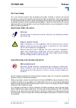
Page 8: ...ve Device This symbol and title inform that electronic boards and their compo nents are sensitive to static electricity Therefore care must be taken during all handling operations and inspections of t...

Page 9: ...is most easily done by touching a metal part of your system housing It is particularly important to observe standard anti static precautions when changing piggy backs ROM devices jumper settings etc I...

Page 10: ...ental requirements This applies also to the operational temperature range of the specific board version which must not be exceeded If batteries are present their temperature restrictions must be taken...

Page 11: ...original cost of purchase if appropriate In the event of repair re funding or replacement of any part the ownership of the removed or replaced parts reverts to Kontron and the remaining part of the o...

Page 12: ...Preface CP RIO3 04S Page xii ID 1036 1669 Rev 1 0 This page has been intentionally left blank...

Page 13: ...CP RIO3 04S Introduction ID 1036 1669 Rev 1 0 Page 1 1 Introduction Chapter 1 1...

Page 14: ...Introduction CP RIO3 04S Page 1 2 ID 1036 1669 Rev 1 0 This page has been intentionally left blank...

Page 15: ...S comes with two Gigabit Ethernet ports and one VGA CRT port on the front panel two COM ports COM1 on the front panel and COM2 onboard two onboard SATA ports for connection to external SATA devices on...

Page 16: ...Introduction CP RIO3 04S Page 1 4 ID 1036 1669 Rev 1 0 1 2 2 Front Panel Figure 1 2 CP RIO3 04S Front Panel CP RIO3 04S...

Page 17: ...IO3 04S Introduction ID 1036 1669 Rev 1 0 Page 1 5 1 2 3 Board Layout Figure 1 3 CP RIO3 04S Board Layout Top View J10A J10B Dual GbE J5 SATA J6 1 1 rJ2 CPCI J13 Peripheral Control J2 COM1 VGA J7 J3 C...

Page 18: ...A devices via a SATA cable COM2 One onboard serial port COM2 implemented as a 10 pin 2 54 mm con nector J3 Peripheral Control One 10 pin peripheral control connector J13 with the following features Fa...

Page 19: ...11 ms pulse duration 500 shocks per direction 6 directions 1 s recovery time Single Shock IEC60068 2 27 30 g acceleration 9 ms pulse duration 3 shocks per direction 6 directions 5 s recovery time Not...

Page 20: ...blications contain information relating to the CP RIO3 04S Table 1 3 Related Publications PRODUCT PUBLICATION CompactPCI Systems and Boards CompactPCI Specification 2 0 Rev 3 0 Kontron CompactPCI Back...

Page 21: ...CP RIO3 04S Functional Description ID 1036 1669 Rev 1 0 Page 2 1 Functional Description Chapter 1 2...

Page 22: ...Functional Description CP RIO3 04S Page 2 2 ID 1036 1669 Rev 1 0 This page has been intentionally left blank...

Page 23: ...7 Figure 2 1 D Sub VGA Connector J7 The following table indicates the pinout of the D Sub VGA connector J7 Table 2 1 D Sub VGA Connector J7 Pinout PIN SIGNAL FUNCTION I O 1 Red Red video signal output...

Page 24: ...mplementation MDI STANDARD ETHERNET CABLE PIN MDI X CROSSED ETHERNET CABLE 10BASE T 100BASE TX 1000BASE T 10BASE T 100BASE TX 1000BASE T I O SIGNAL I O SIGNAL I O SIGNAL I O SIGNAL I O SIGNAL I O SIGN...

Page 25: ...ed as a 10 pin connector J3 The following figure illustrates the RJ 45 serial port connector J2 COM1 Figure 2 3 Serial Port Connector J2 COM1 The following table indicates the pinout of the RJ 45 seri...

Page 26: ...table indicates the pinout of the onboard serial port connector J3 COM2 Table 2 4 Serial Port Connector J3 COM2 Pinout PIN SIGNAL DESCRIPTION I O 1 DCD Data carrier detect I 2 DSR Data set ready I 3...

Page 27: ...inout of the peripheral control connector J13 Table 2 5 Peripheral Connector J13 Pinout PIN SIGNAL DESCRIPTION I O 1 GND Signal ground 2 PWR_5VSTDBY 5V standby power optional I 3 FAN_SENSE Fan speed m...

Page 28: ...ossible space limitations within the system For further information please contact Kontron Note To ensure secure connectivity the SATA connector supports the use of SATA II cables SATA cables with loc...

Page 29: ...rt as well as a compatible and correctly configured CPU board are required Do not plug the CP RIO3 04S in a backplane without rear I O support Failure to comply with the above will result in damage to...

Page 30: ...O_1V9 in lPB_DC bi lPB_DC bi GND 11 NC lPB_DB bi lPB_DB bi 2DCD out lPB_DD bi lPB_DD bi GND 10 NC GND 2TXD in VGA_RED in 2DTR in GND GND 9 NC SATA4TXP in GND VGA_HSYNC in GND SATA5TXP in GND 8 NC SATA...

Page 31: ...1036 1669 Rev 1 0 Page 2 11 Legend for Table 2 7 SATAx Serial ATA port lPx Gigabit Ethernet port VGAx VGA signals COM1x COM1 port COM2x COM2 port PWRx Power Management signals 5V 3 3V Power GPIO_CFG0...

Page 32: ...Functional Description CP RIO3 04S Page 2 12 ID 1036 1669 Rev 1 0 This page has been intentionally left blank...

Page 33: ...CP RIO3 04S Installation ID 1036 1669 Rev 1 0 Page 3 1 Installation Chapter 1 3...

Page 34: ...Installation CP RIO3 04S Page 3 2 ID 1036 1669 Rev 1 0 This page has been intentionally left blank...

Page 35: ...on Ensure that the system main power is removed prior to installing or removing the CP RIO3 04S Ensure that there are no other external voltages or signals being applied to the CP RIO3 04S or other bo...

Page 36: ...nt panel retaining screws 8 Connect all external interfacing cables to the CP RIO3 04S as required 9 Ensure that the CP RIO3 04S and all required interfacing cables are properly secured The CP RIO3 04...

Page 37: ...ose of the CP RIO3 04S as required Warning Care must be taken when applying the procedures below to ensure that neither the CP RIO3 04S nor system boards are physically damaged by the application of t...

Page 38: ...A channel does not spin up check power cables and cabling May also result from a bad power supply or SATA device The SATA connector on the CP RIO3 04S provides only a data connection The power for thi...

Reviews: