


37
23
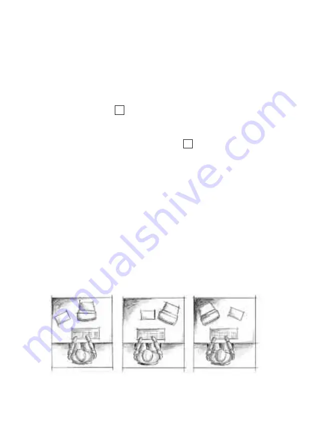
Beispielhafte Anordnung von Bildschirm, Tastatur
und Vorlagenhalter
• Tischplatte mit Plattenrahmen
• Fußplatte mit Gummibelag und Stellgleitern
• Kabelspiral zur vertikalen Kabelführung
CPU-Halterung
(Zubehörteil)
Fußplatte
Steuerung
Kabeldurchlässe
Tischplatte
4 Stellgleiter
Seitl. Fußplatte
(Zubehörteil)
Inbetriebnahme
Stellen Sie sicher, daß der Tisch ordnungsgemäß
aufgestellt ist und daß alle Stecker zur Steuereinheit
fest sitzen, sowie die Leitungen Ihrer Bürotechnik
und des Computers in den dafür vorgesehenen
Kanälen liegen. Schließen Sie den Tisch an das
Versorgungsnetz an. Fahren Sie den Tisch mittels
des Tasters in die niedrigste Position. Von nun an
kann die Steuerung normal betrieben werden (siehe
Anhang).
Ergonomie
Sie sollten die Tischhöhe immer so einstellen, daß
Ihre Ellenbogen sowohl im Sitzen als auch im Stehen
einen Winkel 90° oder größer bilden.
Tip! Achten Sie auf eine blendfreie Aufstellung Ihres
Bildschirms.
Mehr dazu:
www.bueroratgeber.de
2
Kabelspirale
Getting started
Make sure the desk has been set up correctly, that the
plug to the control panel is inserted firmly, and that the
cables from your office equipment and the computer are
in the appropriate trays. Connect the desk to the mains.
Push the button
until the desk has descended to the
lowest position. Pushing the button again raises the
system about 5 mm. It then descends again slowly.
Please do not release the button
until the unit has
finished moving. If this process does not start, the desk
has already been initialised. You can now operate the
control panel as normal (see Appendix).
Ergonomics
You should always adjust the desk height so that your
elbows form an angle of at least 90° whether you are
seated or standing.
Tip! Make sure your screen position does not cause
glare.
⇓
⇓
Example of a properly arranged screen and copyholder
Summary of Contents for ECO.S Series
Page 2: ...Inhalt Seite 1 21 Deutsch Contents Page 22 44 English...
Page 6: ...Steuerung Kabeldurchl sse Kabelspirale Schiebeplatten Riegel CPU Halter 2 Legende...
Page 10: ...Bild 1 Bild 2 6 Bild 1 Bild 2...
Page 12: ...Kabeldurchl sse 8 Bild 3 Bild 4...
Page 14: ...Bild 6 Bild 8 2 Bild 7 10 Bild 6 Bild 7 Bild 8...
Page 16: ...12 Bild 9...
Page 21: ...17 Anhang...
Page 26: ......
Page 29: ...24 Control panel Cable openings Umbilical Sliding top clamp CPU holder Key...
Page 33: ...28 Bild 1 Bild 2 6 Figure 1 Figure 2...
Page 35: ...30 Kabeldurchl sse Figure 3 Figure 4 Cable passages...
Page 37: ...32 Bild 6 Bild 8 10 2 Bild 7 Figure 6 Figure 7 Figure 8...
Page 39: ...34 Figure 9...
Page 44: ...39 Appendix...
Page 48: ...43...


