Konica Minolta PC-410 Installation Manual Download Page 4

E-4

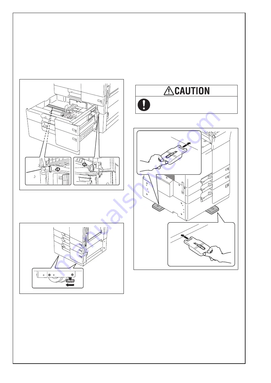
(12) Slide out the drawer from the paper feed cabi-

net.

(13) Slide out the second drawer from the paper 

feed cabinet.

(14) Secure the paper feed cabinet to the machine 

by the fixing bracket A (left) and the fixing 
bracket B (right).
Fixing bracket A: one supplied screw
Fixing bracket B: two supplied screws

Note:

The fixing bracket B can be placed upside down.

(15) Slide the drawers back in.
(16) Move the machine and paper feed cabinet to 

the installation site. Then, adjust the two adjust-
ers at the front to let the paper feed cabinet sit 
on the floor.

(17) Attach the four stabilizers (supplied leg assies) 

as shown in the illustration.

Note:

    • If you proceed to install the Large Capacity Unit 

LU-302/LU-301/LU-204 after this installation, 
do not attach the stabilizer to the left and right 
side of the machine.

    • If you proceed to install the Finisher FS-535/

FS-534SD/FS-534 after this installation, do not 
attach the stabilizer to the left side of the 
machine.

<front and left>

To reduce the risk of injury due to 
unstable equipment, set stabilizers 
before use.

Summary of Contents for PC-410

Page 1: ...loaded mass approx 23 kg 50 11 16 lb 1 Accessory parts Note This manual provides the illustrations of the acces sory parts and machine that may be slightly differ ent in shape from yours In that case...

Page 2: ...feed cab inet hookup harness in position until the machine is attached to the paper feed cabinet 3 Slide the drawer out 4 Remove the shipping materials and protective tape from the inside of the drawe...

Page 3: ...and B of the paper feed cabinet 8 Peel the tape that fixes the paper feed cabinet hookup harness in position 9 Connect the two connectors of the paper feed cabinet hookup harness to the machine 10 Sec...

Page 4: ...inet to the installation site Then adjust the two adjust ers at the front to let the paper feed cabinet sit on the floor 17 Attach the four stabilizers supplied leg assies as shown in the illustration...

Page 5: ...of the paper stack and place the stack into the drawer Note Make sure that the top level of the paper stack does not exceed the MAX paper level indi cator Correct any curl in the paper before loading...

Page 6: ...print produced and check to see if it falls within the specified range Specifications 3 0 mm 1 0 mm Adjusting the paper reference position If the measured width A falls outside the speci fied range en...

Page 7: ...laced near the screws If the width A is greater than the specifications Move the front cover assy to the direction If the width A is smaller than the specifications Move the front cover assy to the di...

Page 8: ...mm Adjusting the paper reference position If the measured width A falls outside the speci fied range enter the correction value using the or key 4 Produce another test print and check to see if width...

Reviews: