background image

AD3435_en


|

  2017-11-17

i

Contents

1 Overview

Major Internal Assemblies.............................................................................................................  1-2
How the Imager Works .................................................................................................................  1-3
Print Sequence ...............................................................................................................................  1-4
Supported Film Sizes .....................................................................................................................  1-5
Mammography Imaging ...............................................................................................................  1-5
Automatic Image Quality and Processing ....................................................................................  1-5
Configure and Monitor the System (Using the Web Portal).......................................................  1-6
Installation, Setup, and Safety......................................................................................................  1-6
User Manual Conventions .............................................................................................................  1-7

2 Basic Operating Tasks

The Display Screen.........................................................................................................................  2-2
Imager Power.................................................................................................................................  2-5

Power Switch Location ............................................................................................................  2-5
Start the Imager.......................................................................................................................  2-6
Emergency Shutdown or Power Loss .....................................................................................  2-7
Restart the Imager...................................................................................................................  2-7

About the Film Cartridges.............................................................................................................  2-8

Replace an Empty Film Cartridge ...........................................................................................  2-9
Load a Different Film Size to Match a Print Request ..........................................................  2-10

Delete All Pending Jobs with Unavailable Media Size or Type ................................................  2-12
Calibrate the Imager for the Loaded Film .................................................................................  2-13

Automatic vs. Manual Calibration ........................................................................................  2-13

Test Prints.....................................................................................................................................  2-14

Make a SMPTE Image Print ...................................................................................................  2-14
Make a Mammography Test Print—Mammography Film Loaded .....................................  2-14

Open or Remove a Cover ............................................................................................................  2-16
Access More Functionality with the Web Portal........................................................................  2-17

Access the Web Portal ...........................................................................................................   2-17

3 Maintenance and Troubleshooting

Overview: Status and Error Messages and Codes ........................................................................  3-2
Preventive Maintenance ...............................................................................................................  3-3
About the Filter .............................................................................................................................  3-3

Replace the Filter.....................................................................................................................  3-4

550 Code and Maintenance Symbol.............................................................................................  3-5
Error Indicators on the Display Screen .........................................................................................  3-6
Recognize and Handle a Calibration Error ..................................................................................  3-6
Handle a Required Restart ............................................................................................................  3-7

Summary of Contents for DRYPRO SIGMA 2

Page 1: ...Publication No AD3435_en 2017 11 17 Operation Manual...

Page 2: ...s reserved No part of this manual may be reproduced or copied in any form by any means graphic electronic or mechanical including photocopying typing or information retrieval systems without written p...

Page 3: ...y Film Cartridge 2 9 Load a Different Film Size to Match a Print Request 2 10 Delete All Pending Jobs with Unavailable Media Size or Type 2 12 Calibrate the Imager for the Loaded Film 2 13 Automatic v...

Page 4: ...Clear Film Jam in Area 2 Error Code 325 Web Portal code 26325 3 29 Clear a Film Jam in Area 2 or 3 Error Code 326 Web Portal code 26326 3 31 Film Jam in Area 3 Error Code 543 or 544 Web Portal code 26...

Page 5: ...image sources such as medical electrical equipment modalities and workstations over the network You can send print jobs simultaneously from multiple image sources The open design lets you connect to m...

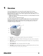
Page 6: ...s 6 Filter door Covers the replaceable filter 7 Exit tray Holds multiple sheets of processed film Extend the exit tray to hold large film 35 x 43 cm 14 x 17 in and 35 x 35 cm 14 x 14 in as it finishes...

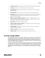
Page 7: ...lers Move the film from the processor area to the exit tray 3 Optics module Writes the image onto the film while the film is moved through the exposure transport 4 Deodorant filter Absorbs potential o...

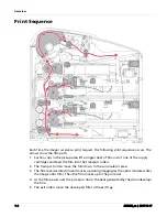
Page 8: ...f the supply cartridges and feed the film into the transport rollers 2 The transport rollers move the film down to the accumulator area 3 The film reverses direction and moves up during imaging as the...

Page 9: ...type to print the mammography job Several mammography specific test prints are provided including a test print for the routine calibration of mammography film for example a density wedge print The de...

Page 10: ...nnections over the network configure features view error messages and access general status information at the Web Portal You can also check film count film size and film type Related topics Access th...

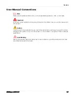
Page 11: ...that affects how you use this manual and this product Caution Cautions point out procedures that you must follow precisely to avoid injury to yourself or others damage to the system or any of its comp...

Page 12: ...off 0 Load the film cartridges Monitor the display screen for status and operating conditions Sometimes it will be necessary to perform preventive maintenance filter replacement and other corrective...

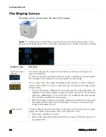
Page 13: ...rror or status condition is present If the imager is on and a 3 digit code does not display the imager is oper ating normally If a print job requires a different film size and or type from the loaded...

Page 14: ...three seconds until the imager beeps twice The test print varies depending on the type of film Pause Important To avoid exposing the film to light do not open the film supply door until the Pause symb...

Page 15: ...ia Size or Type Test Prints Restart the Imager Preventive Maintenance Film Jam Film is jammed from the upper or lower cartridge The error code confirms the film jam and gives direction on where to fin...

Page 16: ...Basic Operating Tasks AD3435_en 2017 11 17 2 5 Imager Power Power Switch Location The power switch 1 is on the lower portion of the imager s back panel 2 H241_0008GC H241_0008GCA 1 2...

Page 17: ...ill be ready to print in 7 minutes The amber power symbol also indicates that the imager is not ready to print The warm up period varies depending on the amount of time the imager has been off and the...

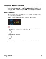
Page 18: ...process when the power was interrupted Restart the Imager If the imager encounters an error that is usually corrected with a restart the display screen shows the Restart symbol Figure 4 A restart is r...

Page 19: ...lm and the lower has 113 Size Type of the Loaded Film To check the size of the loaded film open the film supply door and view the loaded cartridges Note Make sure the Pause symbol is off before you op...

Page 20: ...is empty the film count appears as 0 on the display screen Note Before you load a new film cartridge make sure that the Pause symbol is off When the imager is idle the symbol is off When the film cart...

Page 21: ...film size flashes on the display screen Change the installed film to match the print request M mammography film B blue base film Figure 8 The requested film size flashes and the Film Size symbol indi...

Page 22: ...ading into the imager Set the leading edge 4 on the cartridge guides 5 and then slide the film cartridge into the imager to engage the detents 6 in the bottom of the cartridge 5 Store the removed film...

Page 23: ...s Figure 9 The Film Size symbol indicates that there is at least one job that requires a different size or type of media 2 All print requests for an unavailable media size or type are deleted from the...

Page 24: ...ry calibration and or replace the film cartridge A Not Calibrated message appears on the Web Portal Home screen Manual Calibration 1 Press the Calibrate symbol for the film cartridge upper or lower Fi...

Page 25: ...pper cartridge The Calibration and Power symbols both flash while the test print is in progress 2 When the symbols stop flashing the SMPTE test print is complete Make a Mammography Test Print Mammogra...

Page 26: ...per or lower where the mammography film is loaded for three seconds 2 The film prints with the four density steps The display panel shows the Step 1 values 3 Press the Calibrate symbol again to view t...

Page 27: ...n they are open The imager is not operational when an interlock is open Code 701 alerts you that a cover and an interlock are open and internal power has been removed from the operator accessible area...

Page 28: ...ied with the imager See the note below if using IE 8 or 9 2 In the address field type http imager s IP address Note If you do not know the IP address check with your network administrator or the perso...

Page 29: ...e symbol Error Indicators on the Display Screen Learn about the amber and red error symbols Using the Web Portal to Gain More Information on Errors Learn how and why to access the Web Portal Subsystem...

Page 30: ...the center right The display screen reports 3 digit codes Some codes are associated with symbols on the display screen such as the Film Jam symbol to help you quickly understand the condition At the W...

Page 31: ...CRA Municipality owned and licensed solid waste management facilities are an appropriate disposal option Contact your local or state solid waste authorities to determine if additional disposal require...

Page 32: ...7 Replace the Filter When the filter must be replaced the display screen shows the 449 error code and the Maintenance symbol 1 Open the film supply door 1 2 Remove the filter cover 2 by pulling out fr...

Page 33: ...o reset the imager for the new filter and to clear the Maintenance symbol press and then release the illuminated Maintenance and Calibrate symbols at the same time 550 Code and Maintenance Symbol If t...

Page 34: ...or When the calibration has failed the display screen shows a 624 631 or 632 error and the Calibrate symbol is amber Figure 14 In this example the amber indicator light and Calibration symbol indicate...

Page 35: ...15 The amber Power symbol together with the Restart symbol indicates that you must restart the imager to continue printing 1 Press the power switch on the back of the imager off 2 Press the power swi...

Page 36: ...an continue to print After the jam has been cleared the imager will reprint the image on a new sheet of film Figure 16 In this example the red jam symbol alerts you to the jam and the amber indicator...

Page 37: ...e Web Portal and the Display Screen The 3 digit error and status codes on the display screen are reported at the Web Portal as 5 digit codes The last three digits on the Web Portal codes match the thr...

Page 38: ...info message are returned to the requesting service class user SCU Every error has an associated printer status info message If more than one error exists when a printer N GET request is received a st...

Page 39: ...e switch is enabled The imager is not ready Offline Printing Disabled WARNING PRINTER OFFLINE Printing delivery has been disabled Failed Code will vary Failed See error tables An error occurred that p...

Page 40: ...ure Pause car tridge close requested Not Ready WARNING COVER OPEN The imager is com pleting prints in progress Printer Status Display Screen Web Portal remote Display DICOM Status Description Film Sup...

Page 41: ...ady Invalid film car tridge Invalid Film Tray There is a film cartridge in the film supply but it does not con tain a liner RF tag Install a new film cartridge Ready Normal Tray Info The film cartridg...

Page 42: ...dge fin ishes closing the Pause symbol turns off and you can remove the film cartridge Film Supply State Display Screen Web Portal Display Description Job Manager Status Display Screen Web Portal Dis...

Page 43: ...e Disk Full Load the requested film type and size for jobs that are waiting for media If the error persists call for service 400 06400 MIM Core Image Page Error Resend the print job from the image sou...

Page 44: ...mager Opened During Self Test Replace close the cover Restart the imager If the error persists call for service 449 20449 None Change the deodorant filter 550 20550 None Call service for preventive ma...

Page 45: ...film cartridge into the imager If the error persists call for service 125 21125 or 23125 Film Supply Internal Hardware Failure If the Pause symbol is on press it to cover the film cartridge When the P...

Page 46: ...en If the Pause symbol is on press it to cover the film cartridge When the Pause symbol stops flashing remove the film cartridge from the imager Then reinsert the film cartridge into the imager If the...

Page 47: ...ction 544 26544 Film Jam in Area 3 Clear the jam See the procedure later in this section 123 27123 Optics Internal Hardware Failure Restart the imager If the error persists call for service 931 26931...

Page 48: ...the error persists call for service 551 28551 Processor Heater Failure Restart the imager If the error persists call for service 554 28554 Processor Over Temperature Restart the imager If the error p...

Page 49: ...g AD3435_en 2017 11 17 3 21 Clear Film Jam in Area 2 Error Code 325 Web Portal code 26325 Clear a Film Jam in Area 2 or 3 Error Code 326 Web Portal code 26326 Film Jam in Area 3 Error Code 543 or 544...

Page 50: ...Indications When film is jammed the display screen indicates a jam and an error code that provides guidance on where to check for the jammed film Figure 17 In this example the indicator light shows yo...

Page 51: ...hooting AD3435_en 2017 11 17 3 23 Jam Areas The jam areas are referenced in the instructions to solve the jam H241_0002DC 3 4 1 2 Jam Areas Description 1 Upper supply 2 Lower film supply 3 Film path 4...

Page 52: ...Maintenance and Troubleshooting 3 24 AD3435_en 2017 11 17 Interlocks Interlocks Description 1 Left cover 2 Film supply 3 Top cover 4 Filter cover H241_0002DC 3 4 2 1...

Page 53: ...the film cartridge it might be necessary to manually cover the cartridge See details in the film jam instructions Figure 18 Imager left side Knobs for manual film removal and film cartridge closure H2...

Page 54: ...remove any film Access this area from the front of the imager through the film supply 4 If you have not found the jammed film remove the left cover a Remove the top cover b Turn the knurled knobs 1 2...

Page 55: ...r Film Jam in Area 2 Error Code 302 Web Portal code 26302 1 If the Pause symbol is on press it and wait until it goes off 2 Remove the left cover a Open the film supply door b Remove the top cover c T...

Page 56: ...any misplaced film in the imager b Remove any loose film near in or partially in the cartridge c If the film is not loose carefully turn the exposure transport knob 1 and the vertical transport knob...

Page 57: ...Error Code 325 Web Portal code 26325 1 If the Pause symbol is on press it and wait until it goes off 2 Remove the left cover a Open the film supply door b Remove the top cover c Turn the knurled knob...

Page 58: ...ting 3 30 AD3435_en 2017 11 17 4 If the film is not loose carefully turn the exposure transport knob 1 and the vertical transport knob 2 clockwise to remove the film from the rollers 5 Reinstall close...

Page 59: ...Film Jam in Area 2 or 3 Error Code 326 Web Portal code 26326 1 If the Pause symbol is on press it and wait until it goes off 2 Remove the left cover a Open the film supply door b Remove the top cover...

Page 60: ...ckwise until a film exits the imager 4 If a film does not exit a Reach into Area 2 and remove any film b If the film is not loose carefully turn the exposure transport knob 1 and the vertical transpor...

Page 61: ...r 26544 1 If the Pause symbol is on press it and wait until it goes off 2 Remove any film that is jammed in the exit tray 3 Remove the top cover and remove any films 4 If you have not found any jammed...

Page 62: ...ng 3 34 AD3435_en 2017 11 17 5 Rotate the exit roller knob 1 clockwise until a film exits the imager 6 Pivot the heat shield 1 open and check for jammed film in the processor drum 2 area H241_0002DC 1...

Page 63: ...Maintenance and Troubleshooting AD3435_en 2017 11 17 3 35 7 If necessary carefully rotate the processor drum knob 1 clockwise and remove any film 8 Reinstall close the covers H241_0002DC 1...

Page 64: ...o turn power off and then on If the display screen is still non responsive turn the imager off and contact a qualified service provider Call for Support If you cannot correct a condition and need help...

Page 65: ...othermographic film designed specifically for the imager Spectral Sensitivity of the Film The Laser Imaging Film is infrared sensitive and has been sensitized to the infrared laser diode of the imager...

Page 66: ...Film is not considered hazardous to the environment As a result you can develop recycle and dispose of film with less impact on the environment than if you were using wet developed silver halide films...

Page 67: ...Film can be left on a light box for more than 24 hours In extreme cases in which the light boxes are exceptionally hot equal to or greater than 49 C or 120 F the manufacturer recommends removing them...

Page 68: ...t low level odors and prevent them from dissipating into the work environment To help maintain optimum performance the filters require periodic replacement The imager requires no special venting Heat...

Page 69: ...unter must extend beyond the imager dimensions by at least 31 cm 12 in In addition there must be space in front of the imager to allow access in the event of a service call The recommended table or co...

Page 70: ...noise Less than 48 dB at 1 m during idle or standby Less than 75 dB momentary at 1 m during normal operation Power Requirements A power cord is provided with this equipment All countries must use an A...

Page 71: ...ccess Network Requirements Specifications AD3435_en 2017 11 17 5 3 Caution Changes in the network configuration Connection of additional items to the network Disconnection of items from the network Up...

Page 72: ...n History Revision Date Reason for Change A 2016 03 31 First release B 2016 03 31 Deleted a reference to a machine number C 2017 11 17 Replaced the film path diagram Updated the operating requirements...

Page 73: ...KONICA MINOLTA INC 1 Sakura machi Hino shi Tokyo 191 8511 Japan KONICA MINOLTA INC 2017 Made in the USA KONICA MINOLTA and DRYPRO are trademarks of KONICA MINOLTA INC Pub No AD3435_en Rev C...

Reviews: