Konica Minolta Bizhub C3350 Installation Manual Download Page 3

E-3

V. Accessory parts

* Varies depending on each model and each mar-

keting area.

Note:

In case the FAX Kit is not included as the standard 
equipment, keep the label (Super G3 label) at 
hand. It is necessary for mounting the FAX Kit.

Note:

This manual provides the illustrations of the acces-
sory parts and machine that may be slightly differ-
ent in shape from yours. In that case, instead of 
the illustrations, use the appearance of your 
machine to follow the installation procedure. This 
does not cause any significant change or problem 
with the procedure.

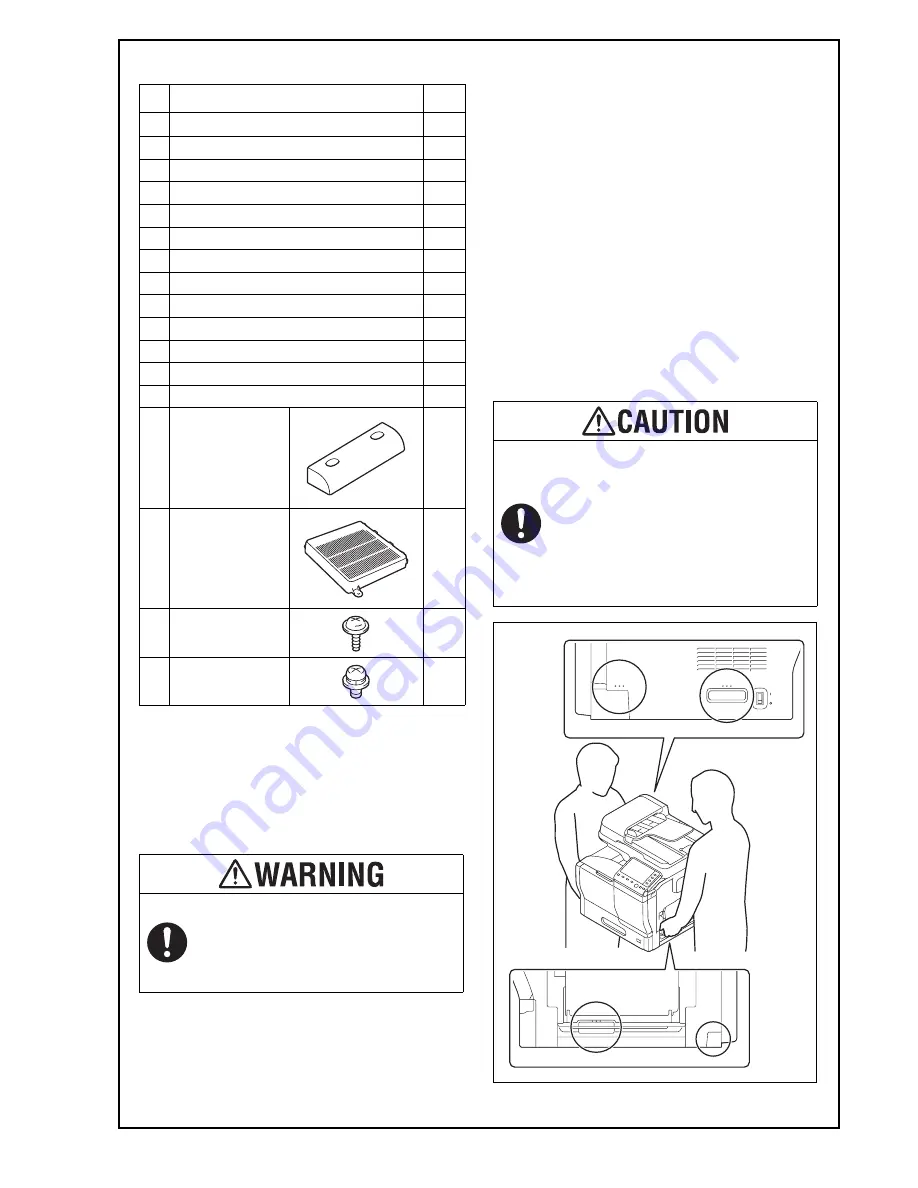
VI. Unpacking the machine

1. Raise and remove the packing carton.
2. Remove the accessory parts and cushions on the 

machine and open the plastic bag covering the 
machine.

3. Assign two or more persons and put their hands 

at the positions indicated in the illustration to 
raise the machine from the box, and place the 
machine on the horizontal and robust place.

No.

Name

Q’ty

1. Safety Information Guide

1

2. Quick start guide

1 set

3. Installation manual

1 set

4. User’s guide CD

1

5. CD-ROM

1 set

6. Paper size label

1 set

7. Label (Legal restrictions on copying) *

1

8. Label (Super G3 label)

1

9. Panel sheet

1

10. Power cord instruction *

1

11. Power cord

1

12. Modular cable *

1

13. Cord clamp *

1

14. Cover A

1

15. Cover B

1

16. Screw A

2

17. Screw B

2

After unpacking, be sure to get rid of the 
packaging materials and keep them out of 
the reach of children.
Putting the head in the plastic bag 
involves danger of suffocation.

Be sure to hold the place specified in the 
User’s Guide or other manuals to transfer 
the machine.
Holding other places than the specified in 
transferring the machine could cause per-
sonal injury due to the drop of the 
machine or other reasons.
(Machine mass: approx. 47.5 kg (104-11/
16 lb))

Summary of Contents for Bizhub C3350

Page 1: ...erform the procedures correctly Optional devices must be installed after com pleting the main unit installation Once the Power Switch is turned ON do not turn OFF it until the installation work has been completed Caution Lifting the machine in an awkward position or transporting it in a poorly balanced position could result in personal injury When transporting the machine assign an adequate number...

Page 2: ... exposed to direct sunlight 6 Avoid a dusty location or a place near volatile and flammable substances 7 Avoid a poorly ventilated place IV Notes on using touch panel Be sure to instruct users on the following points This machine uses a capacitive touch panel When you touch the touch panel use your fin ger or the stylus pen for the capacitive touch panel If you touch the panel using your nail or a...

Page 3: ...at the positions indicated in the illustration to raise the machine from the box and place the machine on the horizontal and robust place No Name Q ty 1 Safety Information Guide 1 2 Quick start guide 1 set 3 Installation manual 1 set 4 User s guide CD 1 5 CD ROM 1 set 6 Paper size label 1 set 7 Label Legal restrictions on copying 1 8 Label Super G3 label 1 9 Panel sheet 1 10 Power cord instruction...

Page 4: ...heet 2 Remove all protective tapes and protective mate rials used for fixing the machine housing 3 Open the automatic document feeder ADF and remove the protective tape and protective mate rial 4 Slide the scanner lock lever to the unlock side and close the ADF 5 Open the front door 6 Pull the fornt lever of a toner cartridge to the left ...

Page 5: ...unit then push the toner cartridge to the back Note Make sure that the toner cartridge is pushed all the way in 10 For the other toner cartridges perform the same procedure as steps 6 to 9 11 Remove protective tapes for the toner cartridges of each color to remove protective films Never touch the electrical contacts of the toner cartridge or the imaging unit as an electrostatic discharge may damag...

Page 6: ...or 14 Open the right door 15 Push up the two levers of the fusing unit cover 16 Remove the protective materials from the fusing section 17 Push down the two levers of the fusing unit cover in step 15 18 Remove the protective materials from the trans fer roller unit 19 Close the right door ...

Page 7: ...per lifting plate is raised push it down by hand to lock it 2 Slide the paper length guide to the appropriate paper size 3 Set paper with the printing side upward and slide the paper width guide to the paper size Note Make sure that the top level of the paper stack does not exceed the MAX paper level indica tor 4 Slide the tray 1 back in IX Mounting the accessory parts 1 Install the supplied cover...

Page 8: ... using the supplied cord clamp One screw removed in step 1 Note This step may not be performed depending on the applicable marketing area 4 Plug the power cord into the power outlet XI Connecting the network cable Connect the main unit and networking equipment HUB using the network cable Note The following shows the recommended network cables that correspond to each communication speed 10BaseT 100...

Page 9: ...if your machine comes with the FAX function as standard After setting the fax target dialing operations may be selected after the switchboard dial tone is detected depending on the destination In this case depending on the switchboard connected to the machine and the type of dial tone received from the switchboard dialing operations may not be avail able If that happens you may be able to avoid th...

Page 10: ...ix the label Super G3 label to the position shown below Note Execute this step only if your machine comes with the FAX function as standard 3 Affix the paper size label to the tray 1 according to the size of the paper used 4 Affix the supplied panel sheet to the surface of the operation panel Note The panel sheet is affixed on customer request The panel sheet must be kept by the customer ...

Reviews: