


Appendix A DESCRIPTION OF PING CYCLE
Appendix A
DESCRIPTION OF
PING CYCLE
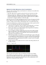
The following diagram explains the timing relationships of the trigger pulse, feedback
signals and the trigger display plots.
Figure 43
Signals display
The timing relationships of the various signals and trigger display are shown. Signal
transitions that are relevant to timing are indicated by an arrow.
This illustration assumes that both ready to transmit and the transmitting feedback
signals are provided by the echo sounder. If ready to transmit is not available, then the
period is estimated based on runtime settings provided. If
transmitting signal
is not
available, it is not possible to know when transmit occurred. In the latter case, it also
means that the trigger display (trigger plot) will not show a red pulse at time of tranmsit.
342435/B
55


