


EN
UAB KOMFOVENT we reserve the right to make changes without prior notice
8
C3.1-16-01
1.4. Temperature Sensors Installation
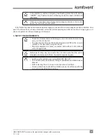
The supply air temperature sensor B1 (1.4 a Picture) is mounted in the air duct in a projected place for it; after
cooler section (if provided). The minimal distance from the duct connection of the unit up to the sensor should
be not less than double diameter of the circular connection or a diagonal of rectangular connection.
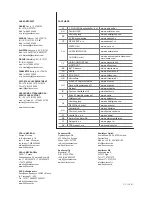
The water temperature sensor B5 (1.4 b Picture) is mounted on the water pipe by screwing it into the pro-
vided hole. The sensor must be thermo insulated!
Supply air temperature sensor B1
Water temperature sensor B5
1.4 a Picture
1.4 b Picture
1.5. Requirements for the installation of the control panel
1. The control console should be installed in a room where the following conditions are ensured:
1.1. ambient temperature: 0
ºC ... 40 ºC;
1.2. relative humidity range: 20 % ... 80 %;
1.3. protection against dripping of water (IP X0).
2. Control panel connection is provided through a hole in the back or bottom side.
3. The panel can be mounted on a flush mounting box or in any other place just screwing two holes on the
fastening surface.
Do not use any other type or size screws but those that are packed toget-
her for control panel mounting. Wrong screws may damage electronics
board.
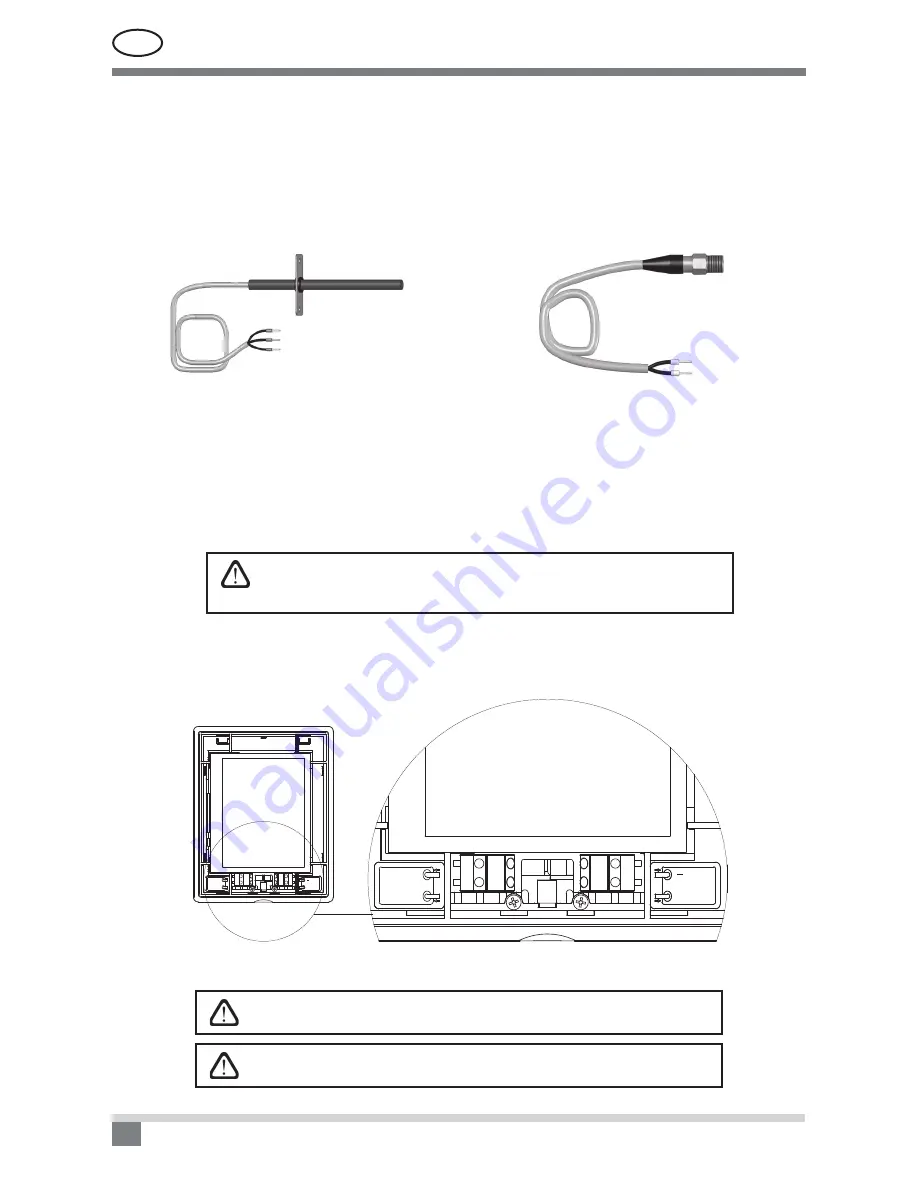
1.6. Control panel connection
The control panel is connected to the connection terminals (see Picture 1.3 a or Picture 1.3 b). The length of the
cable for connecting the panel with the unit may not exceed 150 m.
Yellow (A)
( ) White
(+) Red
Green (B)
Yellow (A)
(+) Red
Green (B)
( ) White
Yellow (A)
( ) White
(+) Red
Green (B)
Yellow (A)
(+) Red
Green (B)
( ) White
1.6 Picture. Control panel connection
Control panel connection and other cable thicknesses are specified in
the wiring diagram!
Remove protective screen tape, before mounting front cover on the con-
trol panel!
Summary of Contents for C3.1
Page 1: ...EN Electrical installation and Operation Manual C3 1 ...
Page 2: ......
Page 18: ......
Page 19: ......


