5
×
NO.0080
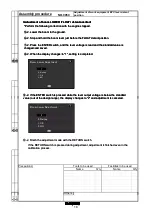
Adjustment of rear view monitor guide line
position
6
×
Assembly procedure
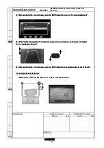
④
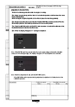
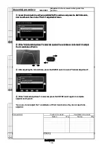
Select [02 Guide Line Position Adjustment] with the UP (
▲
) and DOWN (
▼
) switches and
push the ENTER switch, and the screen moves to the "Guide Line Position Adjustment"
screen.
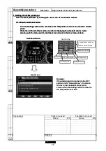
*Detail of each point
Point 1
Point 2
Q'ty
Name
Q'ty
Others
3
×
Precautions
Tools to be used
Name
Facilities to be used
4
×
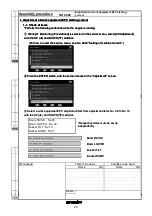
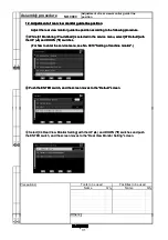
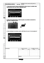
④
Select [02 Guide Line Position Adjustment] with the UP (
▲
) and DOWN (
▼
) switches and
push the ENTER switch, and the screen moves to the "Guide Line Position Adjustment"
screen.
*Detail of each point
Point 1
Point 2
Point 3
Point 4
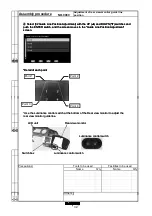
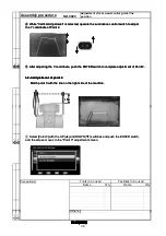
*Use the Luminance control switch at the bottom of the Rear view monitor to adjust the
rear view monitor guide line.
LCD unit
Switch box
Rear view monitor
Luminance control switch
Luminance control switch
Others
1 ×
2 ×
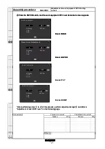
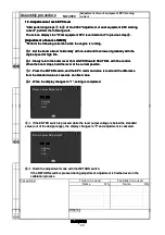
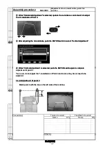
④
Select [02 Guide Line Position Adjustment] with the UP (
▲
) and DOWN (
▼
) switches and
push the ENTER switch, and the screen moves to the "Guide Line Position Adjustment"
screen.
*Detail of each point
Point 1
Point 2
Point 3
Point 4
*Use the Luminance control switch at the bottom of the Rear view monitor to adjust the
rear view monitor guide line.
LCD unit
Switch box
Rear view monitor
Luminance control switch
Luminance control switch
32
Summary of Contents for WA470-7
Page 1: ...WHEEL LOADER Field Assembly Instruction GEN00122 00 WA470 7 SERIAL NUMBERS 10001 and up...
Page 3: ......
Page 42: ......

