background image

1.6. STRUCTURE AND STABILITY OF THE LIFT TRUCK

1-27

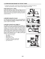
STABLE RANGE OF CENTER OF GRAVITY

For the lift truck to remain stable, the combined center of gravity

of the lift truck must come within a stable range of the center of

gravity, i.e. a triangle formed by three points of the right and left

front wheels in contact with the floor and the center of the rear

axle.
When a position of the combined center of gravity shifts beyond

the front axle, the lift truck will tip over in the forward direction with

the front wheels acting as a fulcrum. On the other hand, when a

position of the combined center of gravity shifts outside of a

stable range of the center of gravity, the lift truck will overturn in

the direction of shifting.

ACTUAL CAPACITY 

The horizontal distance from the position of the center of gravity

of a load on the fork to the upright load backrest of the fork is

called a load center.
Actual capacity means the maximum weight of a load that can be

loaded at a certain load center.
A load capacity chart is given in the name plate. The chart shows

the relationship between the actual capacity and a load center.
As a load center shifts toward the fork tips, so does the position of

the combined center of gravity, too. Therefore, the load has to be

decreased accordingly in the actual operation.
When the lift truck is equipped with an attachment, or when the mast is raised high, the actual capacity is reduced.

Take this fact into consideration in such a case.

LOAD CAPACITY CHART

In the load capacity chart, capacity is shown in relation to load center.

Capacity values are determined according to each model on the

condition of the specifications shown on the plate.
Before proceeding to loading a load, make sure that the load center

and the load are well within the confines of capacity.
When the load is in a complex shape, pull the load closer to the load

backrest so that the heaviest portion of the load comes to the fork

center.
Should a load be loaded beyond the confines of capacity, it would pose a serious danger to the lifting truck as the

rear wheels (for steering) are likely to lift off the ground, causing the operator to lose control of steering.
To make the things still worse, the lift truck will likely tip over while in operation. Therefore, always make sure that

the load is absolutely within the confines of capacity.

LOAD CENTER AND ACTUAL CAPACITY

A nameplate shown at right is just an example. In the actual

operation, follow the instructions on a nameplate of the actual lift

truck.
An example here shows a nameplate for a lift truck which has a

mast of max. fork height of 3.0 m and which is not equipped with any

attachment.

Even when the load center is shorter than 500 mm, the actual capacity is 2,500 kg (2).
It is required to replace the present nameplate with a new one when the present nameplate is broken or has

become difficult to read. In that case, call your Komatsu Forklift dealer asking for a new replacement nameplate.

(1) When the load center is 500 mm

(2) Capacity: 2,500 kg

(1) When the load center is 600 mm

(2) Capacity: 2,250 kg

(1) When the load center is 1,000 mm (2) Capacity: 1,620 kg

Summary of Contents for CX20 Series

Page 1: ...nd shields are properly secured in place WARNING SERVICE MANUAL CX Forklift Truck Federal Environmental Protection Agency EPA Emission Control Compliant S N 130001A CX20 ISSUED APRIL 2008 SM202 Gasoli...

Page 2: ...ponsible for damages due to misuse or inappropriate use of its products Requests for information comments and other inquiries should be sent to Komatsu Forklift USA Inc 14481 Lochridge Blvd Bldg 2 Cov...

Page 3: ...arefully refer to it often and learn the repair testing and adjustment procedures to the best of your ability Please note that some illustrations are generic and may not look exactly like your unit in...

Page 4: ...when seated on the lift truck The serial number faces upwards for ease of iden tification The S6D102E series engine serial number is stamped on the left side of the engine to the left of the oil filt...

Page 5: ...AST DATA FEATURES INDOOR CUSHION TRUCK 2 2 2 2 SPECIFICATIONS MAST DATA FEATURES OUTDOOR PNEUMATIC TRUCKS 2 5 2 3 TRUCK DATA CUSHION TIRE LIFT TRUCKS INDOOR 2 8 2 4 TRUCK DATA PNEUMATIC TIRE LIFT TRUC...

Page 6: ...N PRESSURE PNEUMATIC TIRE 4 24 4 21 CHECK TORQUE CONVERTER STALL SPEED 4 24 4 22 CHECK TORQFLOW CLUTCH ACTUATION PRESSURE CUSHION TIRE 4 25 4 23 CHECK TORQUE CONVERTER STALL SPEED 4 25 4 24 ADJUST INC...

Page 7: ...AND ASSOCIATED PARTS 5 15 5 33 INSPECT BRAKE DRUMS 5 16 5 34 INSPECT BRAKE BACKING PLATES 5 16 5 35 INSPECT LOAD FORKS 5 16 5 36 INSPECT MAST 5 17 5 37 INSPECT FORK CARRIAGE 5 17 5 38 INSPECT LIFT CHA...

Page 8: ...LY ASSEMBLY FLOW CHART 7 3 WEIGHT TABLE COMPONENT ASSEMBLIES AND PARTS 7 4 7 1 MAST 7 5 7 1 1 MAST REMOVAL TYPICAL 7 5 7 1 2 MAST INSTALLATION TYPICAL 7 6 7 2 ENGINE 7 7 7 2 1 ENGINE REMOVAL FROM CHAS...

Page 9: ...ASSEMBLE F2 R1 TRANSMISSION 7 63 7 5 TORQFLOW TRANSMISSION W TORQUE CONVERTER CUSHION TRUCKS 7 67 TRANSMISSION CONTROL VALVE PARTS BREAKDOWN 7 67 TRANSMISSION CONTROL VALVE SPECIFICATIONS 7 68 7 5 1...

Page 10: ...POWER STEERING CYLINDER INSTALLATION 7 128 7 11 POWER STEERING CYLINDER 7 129 POWER STEERING CYLINDER PARTS BREAKDOWN 7 129 7 12 POWER STEERING VALVE ORBITAL 7 130 POWER STEERING VALVE PARTS BREAKDOW...

Page 11: ...OFF VALVE 7 171 7 16 5 SERVICE INFORMATION COMBINATION WORK PORT RELIEF ANTI VOID UNIT 7 172 7 17 TILT CYLINDER 7 173 TILT CYLINDER PARTS BREAKDOWN 7 173 7 17 1 DISASSEMBLE TILT CYLINDER 7 174 7 17 2...

Page 12: ...7 KILOGRAM TO POUND 11 56 11 8 POUND TO KILOGRAM 11 56 11 9 KILOGRAMS PER SQUARE CENTIMETER TO POUNDS PER SQUARE INCH 11 57 11 10 KILOGRAM TO FOOT POUNDS OF FORCE 11 58 11 11 TEMPERATURE FAHRENHEIT T...

Page 13: ...FG45T2 8 10 000 lb capacity pneumatic tire truck long wheelbase 2 spd trans TB45 FG45ST 8 10 000 lb capacity cushion tire truck long wheelbase 1 spd trans TB45 FG45BCS 8 10 000 lb capacity cushion ti...

Page 14: ...enance of TB45E engines in order to comply with the EPA off road large spark ignition LSI engine regulations 1 LABELS REQUIRED AND LABEL LOCATIONS All engines will display the required identification...

Page 15: ...rklift Dealer OWNER S WARRANTY RESPONSIBILITIES As the off road LSI engine owner you are responsible for the performance of the required maintenance listed in your Operation and Maintenance Manual KFI...

Page 16: ...MONTHS OR 3 500 HOURS FOR GENERAL PARTS ECM Catalytic converter Vaporizer Follow the instructions in the Operations Manual concerning any other maintenance programs not required for EPA compliance Fo...

Page 17: ...s in order to comply with current EPA regulations 1 LABELS REQUIRED AND LABEL LOCATIONS All certified S6D102E diesel engines will display the required identification labels 4 as follows S6D102E diesel...

Page 18: ...e for the period of time listed below provided there has been no abuse damage neglect or improper maintenance of your engine Your emission control system may include parts such as fuel injection pump...

Page 19: ...equired maintenance practices and intervals As the heavy duty off road engine owner you should however be aware that KFI may deny your war ranty coverage if your heavy duty off road engine or part has...

Page 20: ...d repair work as they are staffed with trained per sonnel proper tools and are aware of the latest maintenance methods and procedures Owners and others who desire to perform their own work should purc...

Page 21: ...1 SAFETY...

Page 22: ...RULES IN PLACE Do not operate the lift truck if you are fatigued or when you have been drinking or have taken any medication which can make you sleepy When carrying out operation inspection or mainte...

Page 23: ...ional equipment parts or the like on the lift truck or modify the lift truck without prior written consent from Komatsu Forklifts An additional counterweight or unauthorized modification of the lift t...

Page 24: ...may collect Ensure that the tank is securely mounted Do not completely fill the tank to prevent overflow and fire hazard when the LPG expands If there is LPG odor or frost on the fuel tank do not star...

Page 25: ...ollect Store all LPG cylinders OUTDOORS in a secured area and safe from any vehicle traffic NEVER WELD ON AN LPG PRESSURE VESSEL STORAGE TANK OR CYLINDER Ensure that the fuel tank is properly mounted...

Page 26: ...n you are not seated properly or off the seat an accident may happen unexpectedly To forestall such a possible accident the truck is provided with Travel Interlock and Lift Tilt Interlock that make tr...

Page 27: ...ine Always lock them in position after adjusting Adjusting the seat or steering wheel during operation is dangerous as it may cause you to lose your balance or operate the lift truck in an unsafe mann...

Page 28: ...f limited view like a crossing When passing through an area of limited view like a crossing or when running into a narrow path sound the horn and check the surroundings for safety Even if you sound th...

Page 29: ...anks and do not use them if they do not have ample strength to take the weight of the lift truck when loaded Apply the brakes on the truck and block the wheels before driving the forklift into the tru...

Page 30: ...the ground surface and the bottom of the forks so that the bottom of the forks or pallet do not contact the ground surface or the tip of the fork does not stick into the ground when traveling For saf...

Page 31: ...loaded There is danger that the lift truck will tip Reduce speed before turning the lift truck In particular when traveling unloaded the rear of the lift truck is heavy If the lift truck is turned at...

Page 32: ...eat deforming the clutch plates and causing them to malfunction in the worst case PAY SPECIAL ATTENTION TO THE REAR VIEW WITH AN LPG CYLINDER INSTALLED GASOLINE ENGINE LIFT TRUCK The installed LP gas...

Page 33: ...ocks under the tires in addition to normal parking procedures LPG trucks LPG is heavier than air and will sink to the lowest area possible Avoid parking near areas near floor drains or lubrication pit...

Page 34: ...tor s compartment Be careful not to operate the lever by mistake There is danger that the forks or work equipment may cause serious injury KEEP UNAUTHORIZED PEOPLE OUT OF WORKING AREA AND ENSURE A SIG...

Page 35: ...OF SUFFICIENT STRENGTH Always be sure that the pallets and skids have ample strength If broken or damaged pallets or skids are used there is a risk that the load may fall Always check that the load i...

Page 36: ...he forks can collapse Never exceed the max load shown in the load capacity chart on the nameplate DON T HANDLE A LOAD IN AN INSECURE MANNER Make sure that the center of gravity of the load is in line...

Page 37: ...is a risk that the load will be damaged or fall DON T TILT THE MAST FORWARD WITH A LOAD ON THE FORK Do not tilt the mast forward with the load raised Do not raise the load when the mast is tilted for...

Page 38: ...purpose than was originally intended the loading work using the fork or attachments Do not use the forks to open or close the doors of railroad cars or warehouses Do not push any other vehicle Do not...

Page 39: ...ntrol panel where it is easy to see Set the forward reverse lever high low speed lever and work equipment lever each to the neutral position Apply the parking brakes and put stoppers chocks both befor...

Page 40: ...NDLING OF BRAKE OIL It is dangerous if the brakes do not work because in this condition the lift truck cannot be stopped Always do the following Check the level of the brake fluid periodically Always...

Page 41: ...oles it is dangerous if the jet of high pressure oil hits your skin or eyes Always wear safety glasses and thick gloves and use a piece of cardboard or a sheet of plywood to check for oil leakage If y...

Page 42: ...e face of the tire Always have tire inflation work carried out by properly qualified personnel The tire inflation pressure on a forklift truck is several times higher than the pressure on an automobil...

Page 43: ...booster cables When starting using the battery of another lift truck do not allow the two lift trucks to touch Stop the engine before connecting the cables Be extremely careful not to let the cables...

Page 44: ...he battery terminals securely Loose terminals can generate sparks and lead to an explosion When connecting the disconnected battery cables again be sure which is the positive terminal and which is the...

Page 45: ...TO TOW THE LIFT TRUCK 1 The towed lift truck must have an operator 2 Tow the lift truck slowly 3 Raise the carriage and mast channels and secure from moving 4 If another lift truck is used tow the di...

Page 46: ...of the lift truck it is important to distinguish the position of the center of gravity for loads of various shapes CENTER OF GRAVITY AND STABILITY The stability of the lift truck is determined by the...

Page 47: ...a case LOAD CAPACITY CHART In the load capacity chart capacity is shown in relation to load center Capacity values are determined according to each model on the condition of the specifications shown...

Page 48: ...es are applied suddenly there is danger of a large force being applied towards the front which may make the lift truck tip or the load to be expelled When the lift truck is turned a centrifugal force...

Page 49: ...ion for labels are given in the following sections 1 11 3 10 5 7 9 Inside front left stay Inside rear right stay Overhead guard inside right 2 12 Overhead guard inside left On engine 6 Top of radiator...

Page 50: ...he lift truck fall on top of you d Brace yourself with both feet to support your body e Lean in the opposite direction from the direction in which the lift truck is tipping Items b through e are instr...

Page 51: ...assengers allowed 5 Prohibit the operator from standing on the forks Never enter the area under the forks 6 Use caution to avoid getting hand caught in fan not shown 7 Use caution to avoid getting han...

Page 52: ...perate without overhead guard and load backrest Fill fuel or charge battery only in specified place Stop engine when fueling and avoid open flame or sparks and provide adequate ventilation Keep vent c...

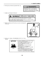
Page 53: ...ift truck Never use the overhead guard to lift the truck 13 Warning for handling LPG FLAMMABLE GAS on LP tank bracket 37B 1QT A030 WARNING REPLACE IF DAMAGED This overhead guard offers reasonable prot...

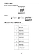
Page 54: ...RDER PART NO 1 09842 A0481 2 3EB 96 A5111 3 3EB 96 A5821 4 3EB 96 A5910 5 3EB 96 A5920 6 3EB 96 A5931 7 3EB 96 A5940 8 3EB 96 A5960 9 3EB 96 A6120 10 3EB 96 A5970 11 37B 1QT A030 12 3EB 96 25520 13 3E...

Page 55: ...to be lighted The law demands that sufficient lighting be provided to ensure safety 1 8 2 HIGH LOAD BACKREST This improves the support for high loads and improves the stability of the load 1 8 3 WIDE...

Reviews:

Related manuals for CX20 Series