73
INSTRUMENTS AND CONTROLS
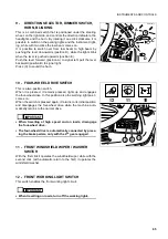
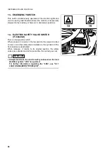
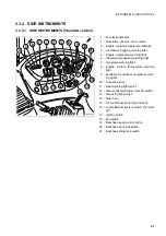
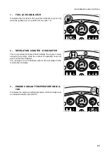
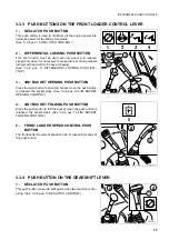
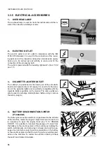
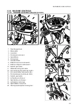
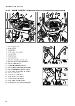
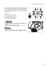
19 - BACKHOE SPEED CONTROL BUTTON
20 - BACKHOE BOOM LOCK SWITCH
21 - BACKHOE SLIDING LOCK SWITCH
This button permits the selection of the oil delivery of the hydrau-
lic pump. Whenever restarted, the machine automatically selects
the POWER mode (LED on), even if when it stopped the select-
ed mode was ECONOMY. This position makes it possible to use
the maximum oil delivery and is indispensable for a correct use
of the backhoe. When the button is pressed (LED off), the
ECONOMY operation mode is selected. To return to the POW-
ER mode (LED on), press the button again. The machine passes
automatically from the POWER to the ECONOMY operation
mode when the forward or the reverse gear are engaged (invert-
er control lever forward or backward). To return to the POWER
operation mode, shift the lever back to the neutral position
IMPORTANT
☞
•
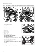
If the machine is equipped with backhoe servo controls, the
switch (19) is positioned on the upper part of the side dash-
board, as shown in Fig. A.
19
20
21
RWA31230
19
20
21
POWER
This switch is used to couple the safety lock with the boom when
the backhoe is not used or when travelling. The safety lock is en-
gaged when the switch is off (led off), while its disengagement
takes place when the switch is on (led on). (See “3.3.6.1 pos. 8”).
IMPORTANT
☞
•
If the machine is equipped with backhoe servo controls, the
switch (20) is positioned on the upper part of the side dash-
board, as shown in Fig. A.
The specific function of the switch (20) can be disabled
through the control locking switch (22).
For further information, see “22 - CONTROL LOCKING
SWITCH (Version with servo controls)”.
19 20
21
22
19
20
21
RWA37770
POWER
22
A
This switch has the function to release the backhoe unit from the
sliding guides, in such a way as to make it possible to change
the position of the backhoe with respect to the machine. The
backhoe unit is generally locked on the guides and the switch is
not operated (led off). When pressed, the switch comes on and
releases the unit from the guides, thus allowing the backhoe to
slide; once the desired position has been reached, press the
switch again to lock the backhoe unit (led off).
IMPORTANT
☞
•
If the machine is equipped with backhoe servo controls, the
switch (21) is positioned on the upper part of the side dash-
board, as shown in Fig. A.
The specific function of the switch (21) can be disabled
through the control locking switch (22).
For further information, see “22 - CONTROL LOCKING
SWITCH (Version with servo controls)”.
Summary of Contents for Avance WB91R-2
Page 2: ......
Page 12: ...10 THIS PAGE WAS INTENTIONALLY LEFT EMPTY ...
Page 21: ...SAFETY AND ACCIDENT PREVENTION ...
Page 56: ...54 THIS PAGE WAS INTENTIONALLY LEFT EMPTY ...
Page 57: ...THE MACHINE AND ITS OPERATIONS ...
Page 124: ...122 THIS PAGE WAS INTENTIONALLY LEFT EMPTY ...
Page 159: ...MAINTENANCE ...
Page 229: ...TECHNICAL SPECIFICATIONS ...
Page 238: ...236 THIS PAGE WAS INTENTIONALLY LEFT EMPTY ...
Page 239: ...AUTHORISED OPTIONAL EQUIPMENT ...

