250
BACKHOE TELESCOPIC ARM
6.5 BACKHOE TELESCOPIC ARM
6.5.1 DESCRIPTION AND CONTROL
6.5.1.1
VERSION WITH STANDARD CONTROLS
6.5.1.2
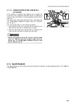
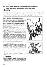
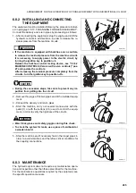
VERSION WITH SERVO CONTROLS
(if installed)
This configuration of the backhoe arm makes it possible to work
with the equipment installed at a variable distance longer than
the distance available with the standard arm.
With the application of this arm (and with extended arm), the
breakout force at the bucket pin is reduced and only lighter loads
can be handled; therefore, it is necessary to install a suitable
bucket (see “6.1 AUTHORIZED OPTIONAL EQUIPMENT”).
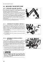
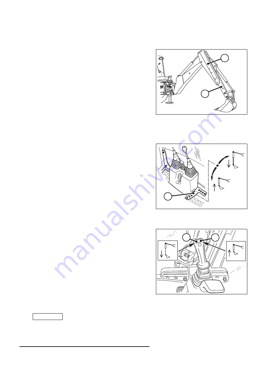
This construction features an external hollow arm (1) into which
the arm (2) supporting the equipment slides on adjustable “V”-
shaped guides.
The sliding of the arm is achieved by means of a double-acting
cylinder controlled by an additional distributor.
1
RWA03550
2
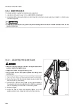
The distributor that manages the telescopic movement is con-
trolled by means of a pedal (3) positioned on the right side of the
backhoe control lever unit; the movements of the levers de-
scribed in “3.3.6.1 (pos.16-17) BACKHOE CONTROL LEVERS”
remain unchanged.?The movements of the telescopic arm are
controlled as follows:
1 - The extension of the arm is obtained by pressing the pedal
(3) with the toe.
2 - The retraction of the arm is obtained by pressing the pedal
(3) with the heel.
RWA35070
3
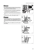
If the machine is equipped with backhoe servo controls, the
movement of the telescopic arm is achieved by means of the
push buttons (4) and (5) positioned on the right joystick lever.
The movements of the main equipment remain unchanged, see
“3.3.6.2 MACHINE CONTROLS (Version with servo controls)”
pos.16 and 17.
The movements of the telescopic arm are controlled as follows:
1 - The extension of the arm is obtained by pressing the push
button (4), while the arm stops when the button is released.
2 - The retraction of the arm is obtained by pressing the push
button (5), while the arm stops when the button is released.
IMPORTANT
☞
•
All the movements of the boom, the arm and the equip-
ment are inhibited when the control safety device is
locked, see “3.3.6.2 MACHINE CONTROLS (Version with
servo controls)” pos. 27.
RWA38100
4
5
Summary of Contents for Avance WB91R-2
Page 2: ......
Page 12: ...10 THIS PAGE WAS INTENTIONALLY LEFT EMPTY ...
Page 21: ...SAFETY AND ACCIDENT PREVENTION ...
Page 56: ...54 THIS PAGE WAS INTENTIONALLY LEFT EMPTY ...
Page 57: ...THE MACHINE AND ITS OPERATIONS ...
Page 124: ...122 THIS PAGE WAS INTENTIONALLY LEFT EMPTY ...
Page 159: ...MAINTENANCE ...
Page 229: ...TECHNICAL SPECIFICATIONS ...
Page 238: ...236 THIS PAGE WAS INTENTIONALLY LEFT EMPTY ...
Page 239: ...AUTHORISED OPTIONAL EQUIPMENT ...


