background image


43.


MCM2082201-01


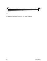
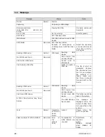
1.1  Message


Message 

Status 

Note 

Freeze 

Normal 

Freeze 


Capturing 

Capturing a JPEG image 


File name and date 
[SSC_0001.JPG 

2011/11/30 

23:59] 

Playing JPEG file 

File  name  and  saved 
time/date 

ALC(1/30) 

ALC is working 

(Shutter speed) 

AWC Done 

AWC has been done 


JPEG Stored 

JPEG file has been stored to USB 
device 


AWC Failed 

Abnormal  AWC has been failed. 

Because  of  overexposure  or 
underexposure,  AWC  has  been 
failed. 


Adjust  the  exposure 
correctly with iris and 
other  items,  and  try 
AWC again. 

Reading USB-device 

Normal 

JPEG save 

Reading 

USB 

device 


No USB-device found 

Abnormal 

USB  device  has 
not been found 


Can't write USB-device 

Cannot  write  to 
USB device 


Can't create a JPEG file 

Failed  to  create  a 
JPEG file. 

 
The  file  of  size  0  is 
generated.  Remove 
the  USB  device  from 
the CCU, and confirm 
the  contents  of  it.   
Please  make  sure 
that  there  is  enough 
free space left on the 
device 
 

Reading USB-device 

Normal 

JPEG load 

Reading 

USB 

device 


No USB-device found 

Abnormal 

USB  device  has 
not been found 


Can't read USB-device 

Cannot  read  USB 
device 

The folder cannot be 
load in the system. 

A  JPEG  file  structure  may  have 

broken 

 
The JPEG file may 
have broken. 

 
The 

message 

is 

displayed  when  the 
format of JPEG file is 
not  supported  in  the 
system. 

Lock 

Normal 

Operation 
of the front 
panel 
switch   

Locked 

Shown  when  the 
switch is pushed. 

Please readjust for White Defects   

Abnormal  Error 

at 

the 
camera 
head 
 

Compensation  of 
white  defects  are 
required. 


Adjustment 

is 

required 
again. 

Please 

contact 

your  dealer  or 

sales 

Summary of Contents for KC-1000

Page 1: ...1 MCM2082201 01 Super High Sensitivity HD Video Camera with Separated Camera Head KC 1000 User s Guide Tentative Komaura Corporation...

Page 2: ...fic to CMOS image sensors 6 3 Name and Function of Parts 7 3 1 CCU Front Panel 7 Front Panel 7 Feature Locations 7 LED s 9 3 2 CCU Rear Panel 10 3 3 Camera Head 12 4 Installation 13 Installing the uni...

Page 3: ...u Operation 18 3 On Screen Menu Description 19 3 1 Scene Files 19 3 2 ALC 22 ALC Mask area settings 26 ALC Mode settings 28 3 3 Picture 31 3 4 Color 32 3 5 Settings 35 3 6 Information 39 4041 On Scree...

Page 4: ...twisted pair cable up to a length of approximately 80 m This enables flexible and inexpensive use even in locations in which installation was difficult in the past or that required large scale constru...

Page 5: ...e the unit outdoor Avoid operating or storing the product in the following locations as these can be a cause of a malfunctions or failure Extremely hot or cold places Operating temperature 0 C to 45 C...

Page 6: ...ower commercially available Do not use a spray type blower to clean the lens Liquid will seep into a lens and eventually cause internal fog Phenomena specific to CMOS image sensors The following pheno...

Page 7: ...te control is optionally available Photo Save current photos to JPEG images Confirm the LED of USB connector is turned on before you save the images to the USB device You can change the preview time w...

Page 8: ...ing the video Please don t unplug the USB device while the system is accessing the USB device IPEG files cannot be displayed if the the camera head is not connected ZOOM Push the switch to change the...

Page 9: ...sor Camera head is connected HDMI HDMI is connected USB slot USB device is accessed Don t unplug the USB device under these conditions Till the LED turns on after you plug the USB device During the LE...

Page 10: ...to the other device on the loop Right When this device is the last on the loop CAMERA Camera connection port The camera connection port of the CCU is the same shape as LAN port Make sure not to conne...

Page 11: ...up when connecting the contact switch an option It becomes impossible to use RS 232C communication OFF Normal operation 4 ON Rear Panel Ext IR receiver valid Front panel Infrared sensor invalid OFF Fr...

Page 12: ...C mount lens can be attached Please use the lens that its projection from the lens mount surface is less than 6 5 mm 0 262 inch CCU connecting port Connect to CCU The camera cable can be attached fir...

Page 13: ...he connector The cable must connect firmly Incomplete connection could cause noises Be sure to hold the connector to unplug Please use in a pair CCU and the camera head which were always enclosed Suff...

Page 14: ...at the property of TCP IP Open TCP IP properties by following procedures in manuals of your PC or OS The screen shot shows example IP address 192 168 1 80 Subnet address 255 255 255 0 Note The IP addr...

Page 15: ...NU to activate the on screen menu The top menu below is shown at the right down corner of the monitor Push MENU again and the on screen menu will close Top menu ALC Picture Color Settings Scene Files...

Page 16: ...ration 0 Blue Hue 0 Blue Saturation 0 Yellow Hue 0 Yellow Saturation 0 Cyan Hue 0 Cyan Saturation 0 Magenta Hue 0 Magenta Saturation 0 Settings HD Format 720 59 94p 3G SDI Level A_B Level A Flip Mirro...

Page 17: ...les Select Scene File Save Scene File Show Detail Settings Information Model Name Serial Number FIRM Version FPGA Version Current Scene File HD Format Date Time IP Address MAC Address Connected Camera...

Page 18: ...target menu and push the rotary switch And then rotate the switch to change the parameter Push the switch and set the parameter While on screen menu is activated you can operate the rotary switch and...

Page 19: ...ings of those 5 scene files are the same Save Scene File Save scene file to the memory 1 to 5 When you change the parameters of the current scene file they are memorized as scene file x temporally If...

Page 20: ...sk Area No Mask Gain 0 0dB Shutter Speed 1 30 Picture WDR OFF Black Level 0 Auto Knee OFF Gamma 0 45 White Clip 109 0 DNR HIGH Enhancer Gain 128 Color WB Mode ATW WB Shift Red 0 WB Shift Blue 0 ATW Sp...

Page 21: ...2 Define Direct Function Rotation ALC Level Push Menu Menu Setup Language English Show Menu Time 10sec Menu Display HD Video Show Capture Time 1sec Time Date YMD Image on screen Time Date OFF Message...

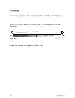
Page 22: ...er Under dark conditions it combines both Gain and Slow shutter and adjusts brightness Mode Select ALC mode There are Full auto Shutter priority and Gain priority When ALC is off you cannot change Mod...

Page 23: ...the condition below ALC Mode OFF ALC Mode Shutter Priority Shutter Limit L Set the lower limit of shutter iris under ALC mode 59 94i p 50i p 1 2 1 2 1 4 1 3 1 8 1 6 1 15 1 12 1 30 1 25 1 60 1 50 1 100...

Page 24: ...Mode OFF ALC Mode Gain Priority Gain Limit L Set the lower limit of Gain under ALC mode within the range of 0dB 65 7dB 0 3 Step Gain Limit L is not available under the condition below ALC Mode OFF AL...

Page 25: ...arger Gain value makes images brighter If ALC Mode is ON Gain is not available Shutter Speed Set the shutter speed If ALC Mode is ON Shutter Speed is not available 59 94i p 50i p When you change the v...

Page 26: ...s backlighting and oblique light S Circle M Circle and L Circle are preset settings Select Manual mode and the 44 blocks of masking area can be changed individually The 1 block in the center is fixed...

Page 27: ...metry No stripes The 1 block in the center is set as no mask area and can be changed to mask area if it is necessary and the others are mask area The current cursor position is dashed line block in th...

Page 28: ...Limit value in order to suppress a flicker of a high intensity images Change Gain Limit value for images that the S N ratio performs important effect When you want to use slow shutter change the valu...

Page 29: ...29 MCM2082201 01 Note To change the value of Shutter Speed open the menu of ALC and select Shutter Speed Light Dark Gain Limit H Gain S Shutter Speed 1 2 1 10000 S...

Page 30: ...lled with shutter speed You can fix the gain to give priority on the S N ratio if the target subject is in the dark environment Note To change the value of Gain open the menu of ALC and select Gain Li...

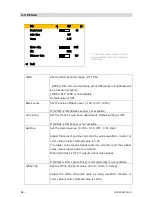
Page 31: ...ng is OFF If WDR is ON Knee is not available Gamma Set the Gamma value 0 35 to 0 55 OFF 0 01 step Adjust the level of gamma correction by using waveform monitor or color video monitor Default value is...

Page 32: ...more DNR level will reduce the noise Default value is HIGH Enhancer Gain Set the Enhancer Gain value 0 to 255 Adjust the level to emphasize outline of the video image Enhancer Gain 0 Enhancer Gain is...

Page 33: ...WB Shift Blue Adjust blue value for white balance at ATW or AWC 30 to 0 to 30 The more value means shift toward blue If WB Mode is Manual WB Shift Blue is not available ATW Speed Set the speed of whi...

Page 34: ...reen Saturation Green saturation is adjusted 30 0 30 Blue Hue Blue hue is adjusted 10 0 10 Blue Saturation Blue saturation is adjusted 30 0 30 Yellow Hue Yellow hue is adjusted 10 0 10 Yellow Saturati...

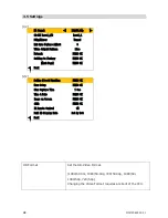
Page 35: ...ory PRESS OK Next Page PRESS OK Back 2 2 Define Direct Function PRESS OK Menu Setup PRESS OK Show Capture Time 1 Sec Time Date PRESS OK Image on Screen PRESS OK JPEG PRESS OK IR Remote Control ON Full...

Page 36: ...Mirror Reverse left to right Flip Mirror Reverse up to down and left to right Ext Sync H phase Adjust Adjustment of H phase of the external synchronizing signal Video Output Pattern Set the video tes...

Page 37: ...INITE 1 Menu Display HD Video Video Password Lock ON OFF 2 1 If Show Menu Time is set to INFINITE the on screen menu keeps showing up In that case please note that items which are set to display ON wi...

Page 38: ...ror message ON OFF Scene File No The number of the current scene file ON OFF See the chapter of On Screen Display for details JPEG Adjust below items Quality Select JPEG picture quality High Mid Low F...

Page 39: ...39 MCM2082201 01 1280x720 pixels 1920x1080 pixels...

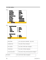
Page 40: ...Next Page 2 2 Connected Camera Head Name xx xxxx Serial xxxxxxxxx Version xx Product Code x x x Paired Camera Head Name xx xxxx Serial xxxxxxxxx Back Model Name The model name is displayed SSC 9000 S...

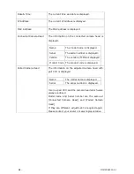
Page 41: ...d Version The version of FPGA is displayed Product Code The product code is displayed Paired Camera Head The information on the adjusted camera head with pair CCU is displayed Name The model name is d...

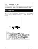
Page 42: ...u can set on off of display for each item individually Status and error message ON OFF The number of the current scene file ON OFF If you add any changing to the settings the value is memorized as a t...

Page 43: ...USB device Can t create a JPEG file Failed to create a JPEG file The file of size 0 is generated Remove the USB device from the CCU and confirm the contents of it Please make sure that there is enough...

Page 44: ...ata error occurred at CAMHED Sec7 Failed to load the initial data Camera operation is available under this error Please wait a while Initializing Normal It is during initial setting A screen becomes a...

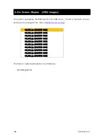
Page 45: ...le List sorting SSC_0001 jpg 2012 07 01 15 20 SSC_0002 jpg 2012 07 01 16 20 SSC_0003 jpg 2012 07 01 17 20 SSC_0004 jpg 2012 07 01 18 20 SSC_0005 jpg 2012 07 01 19 20 SSC_0006 jpg 2012 07 01 20 20 SSC_...

Page 46: ...ronization External synchronization VBS 2 BNC 1 USB USB2 0 1 For still image saving and previewing only Serial port RS 232C D Sub 9pin male 1 Relay interface 2 terminals Unused pin among a serial port...

Page 47: ...stment ALC Full Auto Shutter priority Gain priority Gain AUTO MANUAL 0 78dB Shutter speed 1 2 1 4 1 8 1 15 1 30 1 50 1 60 1 100 1 125 1 250 1 500 1 1000 1 2000 1 4000 1 10000 Gamma correction Variable...

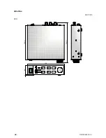
Page 48: ...48 MCM2082201 01 Outline Unit mm CCU 170 1 58 8 18 3 5 4 4 3...

Page 49: ...49 MCM2082201 01 Camera head...

Page 50: ...s are trademarks or registered trademarks of Carina System Other company names and product names are trademarks or registered trademarks of the respective companies KC 1000User s Guide May2014 Komamur...

Reviews: