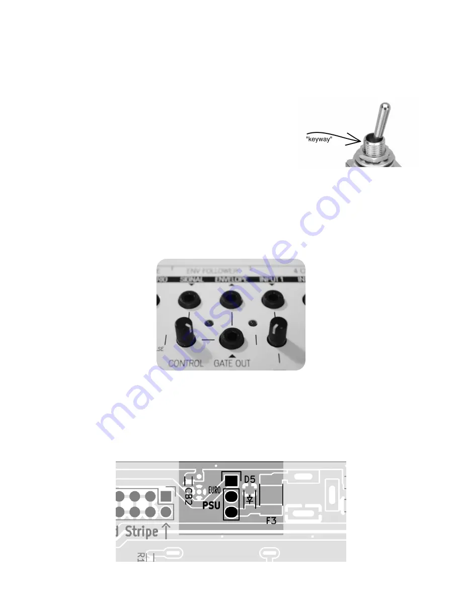
Next, we continue putting in the three types of toggle switches using the front panel to
have them stand straight. Make sure the 'keyway' on the switches is always pointing left
and you don't mix up the SP3T and DPDT switches (they can fit the same footprint). We
can also already place in the LEDs so we don't have to take the front panel out once the
toggle-switches are done. The LEDs should be placed in so that the long leg (anode, +) is
facing left.
Place in:
1) 1 x DPDT (silkscreen: SWITCH_DPDT)
2) 4 x SP3T (silkscreen: SWITCH_SP3T)
3) 3 x SPDT (silkscreen: SWITCH_SPST, woops ^__^)
4) 4 x LED Amber (next to slider pots)
5) 4 x LED Red (remaining LED locations)
Fit the front panel on top of the parts and clamp it on top from the sides. Make sure all
of the switches are fitting through. Once you start soldering in the switches, you have to
push them down with your fingers to make them sit flat against the PCB.
After the swithces it's only the LEDs remaining to be soldered. Before soldering the legs,
make sure the LEDs sit correctly in their openings. You can adjust their position by
wiggling them from their legs.
When the LEDs are in their places:
1) Solder them in
2) Snap off the extra length off the legs
Finally we are going to put a jumper over the power selectors pins to have the Field Kit
powered from the PSU (other option would have been the EuroRack power). Place the 1x2-
Jumper over the 2 innermost pins like also instructed on the silkscreen.


