16 Rear Cover Removal & Daisy Chain Connections
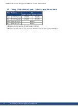
RGM units are provided with 4 wires that pass through the center of the gear output plate to make it easy for
the user to “daisy chain” power and communication from one robot joint to the next. Red (+) and Black (-)
provide 48VDC supply to the next joint. The twisted pair with White (High) and Blue (Low) provide CANopen
communication to the next joint. When bolting two RGM assemblies together in a joint-to-joint configuration
(see section 10), great care must be taken to avoid damaging these wires.
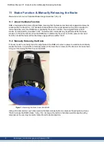
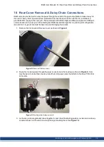
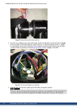
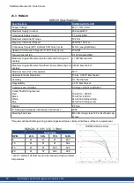
1. Remove the 3 screws and blue rear cover as shown in
.
Figure 8:
Remove the blue cover
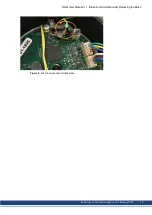
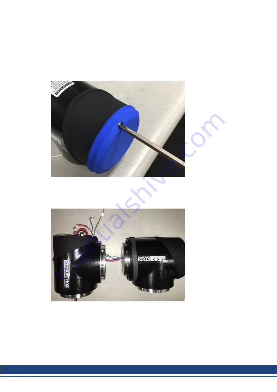
2. Route the incoming wires through the upper access hole in the housing as shown in
. Care
must be taken to route them cleanly around the motor power wires that attach to the drive PCB in this
same area.
Figure 9:
Routing wires between joints
3. As the two joints are gradually drawn together to reach their final bolting position, avoid slack and keep
constant tension on the wires to avoid pinching or mashing them. See
.
RGM User Manual | 16 Rear Cover Removal & Daisy Chain Connections
Kollmorgen | kdn.Kollmorgen.com | February 2019
24


