


P50330 Installation
│
Table of Contents
3
Kollmorgen | May 2012
3
Kollmorgen | April 2013
1
P5000 OVERVIEW
4
1.1
P5000
D
EFINITION
4
1.2
P
ART
N
UMBER
5
1.3
O
THER
S
YSTEM
C
OMPONENTS AND
S
YSTEM
D
IAGRAM
5
1.4
H
OW TO USE THIS MANUAL
6
1.5
W
ARRANTY
7
2
INSTALLING THE P5000
8
2.1
S
AFETY
8
2.2
U
NPACKING AND
I
NSPECTING
8
2.3
S
ELECTING
O
THER
S
YSTEM
C
OMPONENTS
9
2.3.1
Indexer Selection
9
2.3.2
Motor Selection
9
2.3.3
Power Supply Selection
9
2.4
M
OUNTING THE
P5000 10
2.4.1
Connector Removal
10
2.4.2
Heat Sink Mounting
10
2.4.3
Chassis Mounting
10
2.4.4
Mounting Dimensions
12
2.4.5
Mounting Guidelines
12
2.5
W
IRING THE
P5000
12
2.5.1
Introduction
13
2.5.2
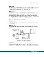
Power Connection
14
2.5.3
Motor Connections
15
2.5.4
Command I/O Connections
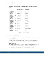
16
2.5.4.1
Step Drive Mode (SW1 ON)
17
2.5.4.2
VCO Mode (SW1 OFF)
19
3
CONFIGURING THE P5000
20
3.1
D
IP
S
WITCH
S
ET
U
P
20
3.1.1
Operation Mode
20
3.1.2
Standby Current Reduction
21
3.1.3
Resolution
21
3.1.3.1
Input Pulse Resolution
22
3.1.3.2
Velocity Trimpot Resolution
22
3.1.4
Mid-Band Resonance Compensation
22
3.1.5
Motor Current
23
3.2
T
RIMPOT
S
ET
U
P
24
3.2.1
Smooth Trimpot
24
3.2.2
Profile Trimpot
24
3.2.3
CW, CCW and Accel Trimpots
24
4
TROUBLESHOOTING 26
4.1
M
AINTAINING THE
P5000 26
4.2
T
ROUBLESHOOTING THE
P5000 26
APPENDIX A: SPECIFICATIONS
27
A.1
E
LECTRICAL
27
A.2
E
NVIRONMENTAL
27
A.3
M
ECHANICAL
28


