background image

AKI-CDA-MOD-10T | ADDITIONAL INSTALLATION TIPS

7.5

Safety

Most of the operator panels are fed with 24 V DC.

4

1

2

4

3

4

Power supply
230 V AC to 24 V DC

Power supply
230 V AC to 24 V DC

Power supply
230 V AC to 24 V DC

Operator panel

Operator panel

Operator panel

Distance?

Small controller with expansion unit

+24 V

+24 V

+24 V

0 V

0 V

0 V

230 V AC

COM1

COM100

Ch0

Ch1

Ch100

Ch101

5355

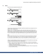
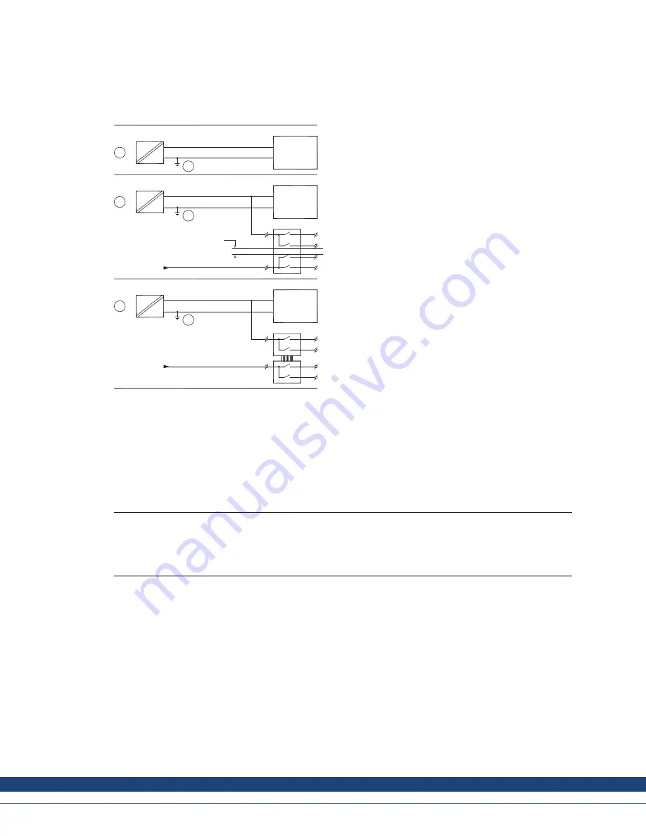
If a power supply that meets safety standards is used and only feeds the operator panel, there is no
problem. See 1 in drawing above.
However, if a 24 V unit that also feeds other units is used, there is reason to be cautious, see 2 in
drawing above. The operator panel does not have insulation that meets safety requirements in the
event of a potential short circuit between 230 V AC and 24 V DC. It is assumed that the 24 V feed is
secure, for example, SELV according to EN 60950 (protection against electric shock) and UL 950.

Note:

Here is an example that explains why a secure 24 V DC feed can be ruined by mixing 24 V relay contacts with
230 V AC relay contacts in a smaller controller. Check that the clearances and creepage distances between
24 V DC and 230 V AC ful

fi

ll EN 60950 or UL 950. If not, input a separate 24 V unit into the operator panel.

If there is a substantial distance between the relay contacts for 24 V DC and 230 V AC, it is OK to use
the same 24 V devices for all feeds. See 3 in drawing above.
Connect 0 V on the 24 V feed to the ground, see 4 in drawing above. This offers three advantages:

Safety is increased. The 24 V feed will not be live in the event of a faulty connection or short circuit
between 0 V (24 V) and 230 V phase.

Transients on the 24 V feed are connected to the ground.

No risk that the 24 V feed is at a high level in relationship to the ground. This is not unusual since
there is high static electricity.

ky

Kollmorgen | October 2014

23

Summary of Contents for AKI-CDA-MOD-10T

Page 1: ...Terminal Installation Manual Edition B October 2014 AKI CDA MOD 10T 10 TouchscreenHMI Keep all manuals as a product component during the life span of the product Pass all manuals to future users owner...

Page 2: ...TICE Technical changes which improve the performance of the device may be made without prior notice Printed in the United States of America This document is the intellectual property of Kollmorgen All...

Page 3: ...eripherals 11 4 Technical Data 5 Chemical Resistance 5 1 Metal Casing 14 5 2 Touch Screen and Overlay 15 5 2 1 Autoflex EBA 180L 15 5 2 2 Touch Screen Surface 15 5 2 3 TouchKeyboard and Screen Protect...

Page 4: ...derstand and use Configuration is carried out on a PC using the Kollmorgen Visualization Builder configuration tool The project can then be transferred and stored in the operator panel itself Various...

Page 5: ...ontact hold the eye open flush with plenty of water and get medical attention The figures in this manual serves an illustrative purpose Because of the many variables associated with any particular ins...

Page 6: ...ed Do not recharge disassemble or dispose of in fire LA BATTERIE PEUT EXPLOSER EN CAS DE MAUVAISE MANIPULATION NE LA RECHARGEZ PAS NE LA D MONTEZ PAS ET NE LA JETEZ PAS DANS LE FEU For use on a flat s...

Page 7: ...n 2 5 Service andMaintenance Only qualified personnel should carry out repairs The agreed warranty applies Before carrying out any cleaning or maintenance operations disconnect the equipment from the...

Page 8: ...3 1 Space Requirements Maximum installation plate thickness 8 mm Space requirements in millimeters when installing the operator panel 100 228 50 100 100 280 50 Note The dimensions onthedrawing are no...

Page 9: ...able surface during installation Dropping the HMI panel or letting it fallmay cause damage 2 To cut a correct opening for the HMI panel use the cut out dimensions in the outline drawing For more infor...

Page 10: ...Controller Power B Ethernet C Connect cable A Connect cable B using an M5 screw and a grounding conductor as short as possible that is sized correctly according to local electrical codes Connect cable...

Page 11: ...2 OtherConnectionsand Peripherals Cables peripheral equipment and accessories must be suitable for the application and its environment For further details or recommendations please refer to the suppli...

Page 12: ...or COM1 RS232 and COM2 RS422 RS485 9 pin D sub contact with RS232 RTS CTS chassis mounted female with standard locking screws 4 40UNC Serialport for COM3 RS232 and COM4 RS422 RS485 9 pin D sub contact...

Page 13: ...cUL The power supply must conform with the requirements for class II power supplies Display TFT LCD with LED backlight 640 480pixels 64 k colors Activearea of display W H 211 2 158 4 mm Operating tem...

Page 14: ...to the following chemicals at room temperature Butanol Nitric acid 3 Hydrochloric acid 5 Nitric acid 10 Isopropyl alcohol Phosphoric acid 43 Sodium hypochlorite 10 Turpentine Note If exposure to any o...

Page 15: ...tchup Caustic soda 40 1 Methanol Trichloroacetic acid 50 Cutting oil Nitric acid 10 White Spirit Cyclohexanol Paraffin oil Windex 1 Diacetone alcohol Persil powder in solution 1 Wisk Diesel Petroleum...

Page 16: ...lex EBA 180L Outdoor Use In common with all polyester based films Autoflex EBA 180L is not suitable for use in conditions of long term exposure to direct sunlight Note The layer structure of the touch...

Page 17: ...Base T shielded RJ45 4 COM 3 4 Communication Ports 6 2 Communication Ports Serial port 9 pin female Serial port 9 pin female Pin COM1 COM2 COM3 COM4 1 RS422 Tx RS485 Tx Rx RS422 Tx RS485 Tx Rx 2 RS23...

Page 18: ...ANEL DRAWINGS 6 3 AKI CDA MOD 10TOutline USB host SD memory card slot Expansion port COM3 RS232 COM4 RS422 RS485 COM1 RS232 COM2 RS422 RS485 Ethernet 24 V DC 209 9 9 7 44 228 max 8 mm 262 9 9 280 ky K...

Page 19: ...ccording to local electrical codes between the operator panel s chassis and the closest grounding point on the door see 3 in drawing above 3 Connect a strong but short grounding braid between the door...

Page 20: ...thernet unit has its shield directly grounded or grounded via a capacitor Note In many cases connecting the shielded Ethernet cabling to the chassis at bothends is inappropriate Hum or grounding loops...

Page 21: ...end of the shield to the ground via a 0 1 F 250 V plastic capacitor Both ends are then connected to the ground in terms of HF but only connected to the ground at one end in terms of LF thus avoiding t...

Page 22: ...itive to heat The lifespan of an electrolytic capacitor is cut in half with an 8 10 C increase in temperature A 15 20 C temperature increase results in a quarter of the lifespan etc Rittal has a good...

Page 23: ...example SELV according to EN 60950 protection against electric shock and UL 950 Note Here is an example that explains why a secure 24 V DC feed can be ruined by mixing 24 V relay contacts with 230 V A...

Page 24: ...example a USB memory stick keyboard or similar device is plugged in If a number of units are connected that have a 0 V and a ground connection and these are connected to various grounding points ther...

Page 25: ...hield must be grounded at one end The other end is usually grounded but with longer distances or when there is a difference in the ground potential the shield should be connected to the ground via 0 1...

Page 26: ...Tap anywhere on screen or touch calibrate will start in 10 seconds 5 Press finger on screen again to enter the service menu The Service Menu displays Note Additional information about the Service Menu...

Page 27: ...y right clicking on the System option in the Project Explorer and select Add HMI Device to display a list of HMI panels that Kollmorgen has available Double click on the project to launch KVB and auto...

Page 28: ...arketplace advantage For assistance with your application needs visit www kollmorgen com or contact us at North America Europe Asia KOLLMORGEN KOLLMORGEN Europe GmbH KOLLMORGEN 203A West Rock Road Pem...

Reviews: