Koldwave 5KK14BEA2AA00 Service Manual Download Page 59

page 

59  

Service Manual

5KK14BEA2AA00 / 5KK21BGA2AA00 / 5KK30BGA2AA00

REFRIGERANT SYSTEM REPAIR

Brazing

•  In the event of a leak, obstruc on, or trouble in the refrigerant system of the unit, 

replace or repair the defec ve component. A er replacing defec ve component, 
braze all connec ons.

1) Proper brazing techniques
•  When brazing, use a slightly reduced fl ame. Oxyacetylene is commonly used since 

the fl ame condi on can be easily judged and adjusted. Unlike gas welding, a sec-
ondary fl ame is used for brazing. Properly preheat the base metal according to the 
shape, size and thermal conduc vity of the brazed fi 

  ng.

•  The most important point in fl ame brazing is to bring the en re brazed fi 

  ng to 

a proper brazing temperature. Care should be taken not to cause overfl ow of the 
brazing fi ller metal, oxida on of the brazing fi ller metal, or fi ller metal deteriora-
 on due to overhea ng the fl ux.
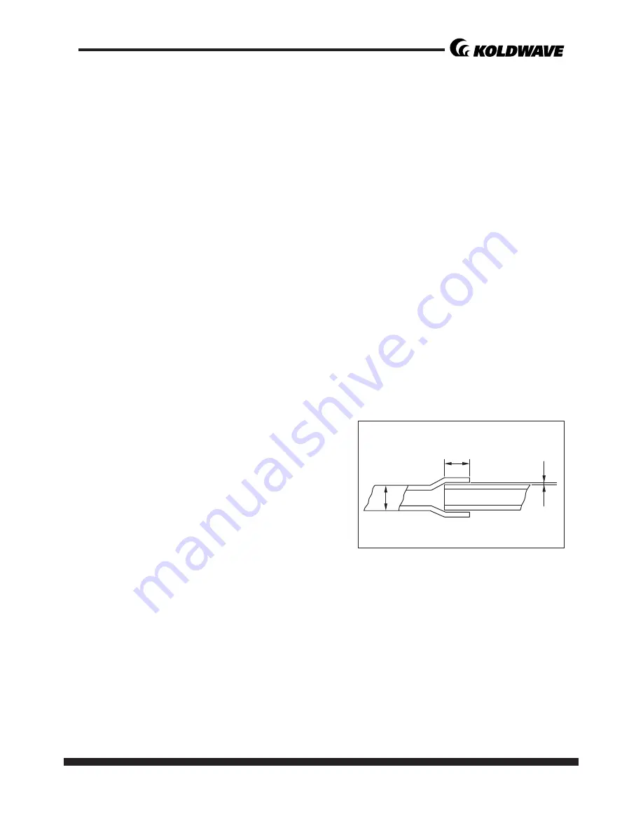
2) Brazed fi 

  ngs and fi 

  ng clearance

•  In general, the strength of the brazing fi ller metal is lower than that of the base 

metal. As such, the shape and clearance of 
brazed fi 

  ngs are very important. Concern-

ing the shape of brazed fi 

  ngs,  adhesive 

area must be maximized. In addi on,  the 
clearance of the brazed fi 

  ng must be mini-

mized so that the brazing fi ller metal will 
fl ow into the fi 

  ng via capillary ac on.

Clearance

Clearance From The Pipe Fing and Tubing.

0.001~0.003 in
(0.025~0.075 mm)

a

a

Summary of Contents for 5KK14BEA2AA00

Page 1: ...page 1 KOLDWAVE Portable Air Condi oners 5KK14BEA2AA00 5KK21BGA2AA00 5KK30BGA2AA00 SERVICE MANUAL ...

Page 2: ...eris cs CONSTRUCTION 9 Internal Structure REFRIGERANT SYSTEM CONSTRUCTION 12 Compressor Compressor lubrica on Condenser Capillary Tube Evaporator Accumulator ELECTRICAL SYSTEM 18 Circuit Diagram Control panel Program Se ng Controller Board Control Specifica ons Self Diagnos c Codes Compressor Evaporator Fan Motor Condenser Fan Motor Capacitor Molded Case Circuit Breaker Magne c Contact Thermal Rela...

Page 3: ... ng chart DISASSEMBLY For 5KK14BEA2AA00 38 Disassembly Control panel removal Electrical parts and relay board removal Fan motor removal DISASSEMBLY For 5KK21BGA2AA00 45 Disassembly Control panel removal Electrical parts and relay board removal Fan motor removal DISASSEMBLY For 5KK30BGA2AA00 52 Disassembly Control panel removal Electrical parts and relay board removal Fan motor removal REFRGERANT S...

Page 4: ...r cular areas or objects 2 The 5KK14BEA2AA00 5KK21BGA2AA00 5KK 30BGA2AA00 has the following features 3 The innova ve design of the KK14BEA2AA 00 5KK21BGA2AA00 5KK30BGA2AA00 has resulted in one compact unit replacing the need for two separate units 4 With the whole cooling system built into one compact unit the 5KK14BEA2AA00 5KK21BG A2AA00 5KK30BGA2AA00 requires no piping and can be easily transpor...

Page 5: ...page 5 Service Manual 5KK14BEA2AA00 5KK21BGA2AA00 5KK30BGA2AA00 SPECIFICATIONS Exterior Dimension Diagram 5KK14BEA2AA00 4 36 2 2 9 12 5 5 9 36 2 17 5 19 8 13 1 12 5 6 20 ...

Page 6: ...6 page Service Manual 5KK14BEA2AA00 5KK21BGA2AA00 5KK30BGA2AA00 5KK21BGA2AA00 22 1 17 3 16 3 7 8 7 1 4 8 36 4 5 6 1 9 16 3 5 9 42 1 20 24 4 ...

Page 7: ...page 7 Service Manual 5KK14BEA2AA00 5KK21BGA2AA00 5KK30BGA2AA00 5KK30BGA2AA00 4 7 6 2 6 2 2 6 15 7 4 0 15 2 22 1 5 36 4 21 O D Ø 5 2 29 4 5 1 42 2 ...

Page 8: ...cs 1 2 3 Ambient temperature range F C 64 113 18 45 64 113 18 45 64 113 18 45 Se ng temperature Room cool mode F C 64 86 18 30 64 86 18 30 64 86 18 30 Se ng temperature Spot cool mode F C 32 86 0 30 32 86 0 30 32 86 0 30 Applica on Area Room cool mode m 377 35 527 50 743 70 Refrigerant Type R 410A R 410A R 410A oz g Toshiba 15 9 451 LG 15 5 440 42 3 1200 44 4 1250 Design Pressure Hi Low Psig Toshi...

Page 9: ...ndenser Condenser Motor Evaporator Cooling Air Duct Condenser Air Outlet Control Box Relay Board Capacitor Drain Tank Drain Tank Switch Compressor Locking Swivel Caster Caster Rear Eva Scroll Control Panel Evaporator Motor CONSTRUCTION Internal Structure 5KK14BEA2AA00 ...

Page 10: ...5KK30BGA2AA00 Control Panel Eva Scroll Drain Tank Drain Tank Switch Condenser Condenser Motor Control Box Relay Board Capacitor Caster Rear Locking Swivel Caster Compressor Evaporator Evaporator Motor Cooling Air Duct Condenser Air Outlet 5KK21BGA2AA00 ...

Page 11: ...21BGA2AA00 5KK30BGA2AA00 Control Panel Eva Scroll Condenser Control Box Relay Board Capacitor Caster Rear Locking Swivel Caster Compressor Drain Tank Switch Drain Tank Evaporator Eva Filter Evaporator Motor Cooling Air Duct Cowl 5KK30BGA2AA00 ...

Page 12: ... 5KK14BEA2AA00 5KK21BGA2AA00 5KK30BGA2AA00 Flow of Refrigerant Condenser Air Outlet Condenser Motor Compressor Accumulator Evaporator Capillary tube Drier Condenser REFRIGERANT SYSTEM CONSTRUCTION 5KK14BEA2AA00 5KK21BGA2AA00 ...

Page 13: ...page 13 Service Manual 5KK14BEA2AA00 5KK21BGA2AA00 5KK30BGA2AA00 Compressor Accumulator Evaporator Capillary tube Drier Condenser 5KK30BGA2AA00 ...

Page 14: ...o mechanisms the drive mechanism compressor motor and the compression mechanism compres sor When the rotor sha of the motor drive mechanism turns the roller com pression mechanism rotates to compress the refrigerant To Condenser Accumulator Strainer From Evaporator Blade Discharge Valve Oil Lubricator Roller Cylinder Rotor Stator Terminal ...

Page 15: ...of the cylinder 3 The discharge valve remains closed 3 Discharge 1 The pressure in the cylinder exceeds that in the discharge chamber and the dis charge valve opens 2 On the suc on side refrigerant suc on con nues 4 Comple on of compression 1 When compression is completed all of the refrigerant has been drawn from the suc on chamber 2 Opera on then returns to step 1 Start of compression and the ab...

Page 16: ...pplied to the lubrica on groove for each sha journal lubrica ng the bearing In this lubrica on system oil enters into each bearing separately and returns to the oil reservoir This system effec vely pre vents bearing temperature increases and offers high reliability In addi on the specially treated sha jour nal keeps the bearing from being damaged during high temperature opera on Condenser 1 The cond...

Page 17: ...ger covered with slit fins Heat is removed from the air being pulled across the evaporator by the centrifugal fan The resul ng cool air is expelled through the cooling air ducts Accumulator The accumulator is mounted on the suc on gas pip ing between the evaporator and the compressor The accumulator separates the liquid refrigerant from the gas refrigerant allowing only the gas refrigerant to enter...

Page 18: ...18 page Service Manual 5KK14BEA2AA00 5KK21BGA2AA00 5KK30BGA2AA00 ELECTRICAL SYSTEM Circuit Diagram 5KK14BEA2AA00 5KK21BGA2AA00 TH1 TH2 TH3 DRAIN PUMP ...

Page 19: ...page 19 Service Manual 5KK14BEA2AA00 5KK21BGA2AA00 5KK30BGA2AA00 5KK30BGA2AA00 DRAIN PUMP option RELAY RELAY POWER 1P AC 208 230V AC115 POWER 1P AC 208 230V AC115 ...

Page 20: ...w speed If POWER BUTTON is pressed during opera on unit stops 2 BLOWER BUTTON Changes fan speed from LOW to HIGH when pressed 3 SPOT COOL BUTTON Ac vates compressor and begins producing cool air 5 seconds a er bu on is pressed Regulates temperature based on outlet cool air temperature 4 ROOM COOL BUTTON Ac vates compressor and produces cool air 5 seconds a er bu on is pressed Regulates temperature...

Page 21: ...on stops when ALARM light is ac vated blinking longer than 3 minutes 7 CURRENT TEMP Room cool mode displays current room temperature in display in Fahrenheit SPOT COOL Mode displays outlet cool air temperature during normal opera ons In order to change F to C press SPOT COOL and ROOM COOL bu ons together for 2 seconds C will blink 2 mes and the figure will change to C ALARM codes blink and are disp...

Page 22: ...ven on sensor Temperature Correc on Temperature Correc on 1 5minutes control is available per 1 minute 1 c 5 c Descrip on the range of se ng Temperature Se ng Program Se ng Auto restored when no se ng is made in each mode Power Switch Target Temperature ON OFF when keep depressing more than 1 seconds Keep depressing more than 3 seconds Delay me Change Devia on temperature se ng Change Temperature ...

Page 23: ...l assembly 1 Power supply requirements The 5KK14BEA2AA00 requires a single phase 115 V 60 Hz power supply while the 5KK21BGA2AA00 5KK30BGA2AA00 requires a single phase 208 230 V 60 Hz power supply 2 Relay board fuse The relay board fuse is the only serviceable component on the relay board assem bly This fuse provides protec on against damage to the step down transformer The fuse must be replaced w...

Page 24: ... TH2 IN TEMP SEN SOR 10 k ohm at 77 F 25 C 181 F 83 C or more 29 F 34 C or less TH2 TH3 ICE TEMP SEN SOR 10 k ohm at 77 F 25 C 181 F 83 C or more 29 F 34 C or less TH3 Symbol Signal Specifica on Func on Connector CO Comp Overload On Between 10 to 20 mA at DC12 V Off No signal On Ac vates Defect control Contact Normally open LED shows CO Output signal ON CO FU External Pump Failure On Between 10 to 2...

Page 25: ...d turns on opera ng the compressor Specifica ons RL4 Compressor On Off relay output 5 A at AC 250 V 3 An freeze control An freeze controls turns the compressor on and off by turning the RL4 relay on in accordance with the freeze protec on thermistor TH3 temperature As a result decreases in cooling performance due to frost buildup on the evaporator are prevented Compressor off condi ons Freeze protec o...

Page 26: ...croprocessor contains a feature that automa cally restart the unit a er power is lost and regained and also has memory to store and recover opera on status in the even of a power loss Status of memory during power interrup on When the input power is off the status items below are saved in the memory Running status on or off Opera ng mode Cool mode or fan only mode Set temperature Temperature mode F ...

Page 27: ...tlet tempera ture sensor has a loose or broken connec on Contact a qualified service agent Abnormal tem perature sensor value TH2 Inlet temperature sensor has a loose or broken connec on Contact a qualified service agent Compressor over loaded Ambient temperature is too high Unstable voltage supply Defec ve compressor Do not use the air condi on er if ambient temperature is higher than 45 C 113 F Co...

Page 28: ...ons 2 Compressor overload relay The compressor overload relay is used to protect the compressor motor The relay interrupts the flow of current when there is an overload condi on and high temperature builds up in the compressor Rated Voltage Rated Output 5KK14BEA2AA00 115V 1175W 5 5KK21BGA2AA00 208 230 V 2000W 1980W 5KK30BGA2AA00 208 230 V 2700W 2715W 5 Run capacitor AUX MAIN R S C COMPR MOTOR Inner...

Page 29: ...e same me The following table shows the specifica ons of the fan motor used for each model NOTE An internal overload relay is used to protect the fan motor This relay is built into the fan motor and interrupts the flow of current when there is an over current situa on or if abnormally high temperature builds up in the fan motor Condenser Fan Motor The fan motor is a single phase induc on type The mo...

Page 30: ...in the evaporator outlet piping and detects low temperature on the evaporator as a resistance value Check capacitance Capacitor Rated Voltage Capacitance 5KK14BEA2AA00 Compressor 250 v 45uF Evaporator Fan Motor 450 v 10uF Condenser Fan Motor 450 v 3 5uF 5KK21BGA2AA00 Compressor 370 v 50uF Evaporator Fan Motor 450 v 8uF Condenser Fan Motor 450 v 8uF 5KK30BGA2AA00 Compressor 370 v 50uF Fan Motor 450...

Page 31: ...stem uses a 250 V 0 1 A ra ng micro switch for this func on When approximately 3 17 gal 12 L of drain water accumulates in the drain tank the drain tank base plate which is supported at fulcrum a is pushed down in the direc on of the arrow When the drain tank base plate is forced down por on A located at the top of the drain tank base plate turns off micro switch contacts 1 2 Evaporator Drain Pan P...

Page 32: ... separately Air adapter fits over the condenser to duct condenser air to the unit to improve cooling efficiency 1 Remove air adapter from carton 2 Place air adapter on the side of air condi oner 3 Use screws enclosed inside of box with air adapter to install the adapter on the air condi oner as shown in Figure 6 1 Remove the power cord holder from the accessory pack 2 Place the power cord holder on t...

Page 33: ...osed inside of box with cool air outlet hose s to install the cool air outlet hose s on the air condi oner as shown in Figure 5 Op onal A warm air top exhaust duct can be purchased separately Exhaust duct fits over the top exhaust fan duct improving cooling efficiency allowing hot air to be exhausted to another loca on 1 Remove duct from carton 2 Place duct on the top of air condi oner 3 Use screws e...

Page 34: ...r 3 Use screws enclosed inside of box with cool air outlet hose s to install the cool air outlet hose s on the air condi oner as shown in Figure 11 POWER CORD HOLDER DISCHARGE DUCTS SUPPLY AIR DUCT Figure 8 Figure 7 Figure 9 Figure 11 Figure 12 A B C Back and Le Side View Condenser filter Power cord holder Caster Electrical access panel 1 Remove the top fan exhaust flange from carton 2 Place the top...

Page 35: ...tlet grilles 8 DO NOT use the unit in areas where it will be exposed to rain or water 9 NEVER unplug the unit while it is opera ng 10 DO NOT place any foreign objects on the unit 11 DO NOT operate the unit with wet or damp hands 12 DO NOT allow chemical substances to come into contact with the unit 13 DO NOT operate the unit in the presence of flammable substances or vapors such as alcohols pes cid...

Page 36: ... electrical outlet 20 Regularly clean the filters to maintain efficiency If the filters are not cleaned regularly the units output performance and efficiency will decline and energy consump on will increase 21 DO NOT operate the unit with a damaged power cord or plug a er it malfunc ons has been dropped or damaged 22 Only use in the upright posi on on an even flat surface Unit must be posi oned at least ...

Page 37: ...bient air cannot be properly cooled if the filter is dirty and not regularly cleaned 2 Compressor will not work if the unit isturned off and on quickly 3 The ambient air tempera ture may be too high 1 Clean the filter 2 Wait 2 minutes a er unit is turned off before turning the unit back on 3 The temperature of the compressor can be higher when the ambient tem perature is too high The compressor will n...

Page 38: ...BEA2AA00 Disassembly 1 Remove the drain tank 2 Take out the four 4 screws and then remove the cooling air duct 3 Take out the three 3 screws and then remove the electric cover 4 Off the circuit breaker For safety Cooling Air Duct Screws 4 Drain Tank Screws 3 electric cover Circuit Breaker ...

Page 39: ...en 7 screws Un fasten two 2 screws to a half point Pull the front panel forward 6 Disconnect the connector from the control panel and then remove the front panel 7 Take out the five 5 screws and then remove the upper panel Screws 7 Screws 2 Front Panel Connector Control panel Screws 5 ...

Page 40: ...from the right side panel 10 Take out the ten 10 screws and then remove the Right side panel 11 Remove the air filter from the le side panel 12 Take out the eight 8 screws and then remove the Le side panel Screws 5 Back Cover Screws 10 Right Side Panel Air Filter Screws 8 Le Side Panel Air Filter Be careful not to damage temperature sensor CAUTION ...

Page 41: ...page 41 Service Manual 5KK14BEA2AA00 5KK21BGA2AA00 5KK30BGA2AA00 1 Take out the four 4 screws and then remove the control panel Screws 4 Control Panel Control Panel Removal ...

Page 42: ...rical parts and relay board removal 5KK14BEA2AA00 MCCB Mold Case Current Braker OCR Over Current Relay Fan Motor for Condenser Compressor R C MC Magne c Contactor Data Cable Connector TH1 Capacitor For Compressor R Compressor S C Condenser Motor TH2 TH3 Full Drain Switch ...

Page 43: ...ee 3 bolts of evaporator top cover 2 Loosen the set screw with a hex key and then remove the evaporator fan 3 Take off the five 5 bolts of the Eva scroll and then remove the Eva scroll 4 Loosen the set screw with a hex key and then remove the condenser axial fan 5 Take off the four 4 hex bolts from the condenser motor bracket and then remove the condenser fan motor 6 Take off the four 4 hex bolts from...

Page 44: ...ervice Manual 5KK14BEA2AA00 5KK21BGA2AA00 5KK30BGA2AA00 5KK14BEA2AA00 Control Box Capacitor for Compressor Cable Tie Stand Off Relay Board MC Magne c Contactor OCR Over Current Relay MCCB Mold Case Current Braker ...

Page 45: ...e drain tank 2 Remove two 2 support lines and remove front panel 3 Take out the eight 8 screws and then remove the cooling air duct 4 Take out the three 3 screws and then remove the service panel 5 Off the circuit breaker For safety Cooling Air Duct Screws 8 Front Panel Drain Tank Screws 3 Service Panel Circuit Breaker ...

Page 46: ...nd then remove the upper panel 7 Unfasten the connector from the control panel and then remove the front panel 8 Remove the air filter from the back panel 9 Take out the two 2 screws and then remove the back plate panel Screws 14 Upper Panel Control panel Connector Screws 2 Back Plate Panel Air Filter ...

Page 47: ...s and then remove the back cover panel 11 Take out the four 4 screws Unfasten two 2 screws to a half point and then remove the low cover panel 12 Take out the eight 8 screws and then remove the right side panel Screws 8 Back Cover Panel Low Cover Panel Screws 4 Screws 2 Screws 8 Right Side Panel ...

Page 48: ...EA2AA00 5KK21BGA2AA00 5KK30BGA2AA00 13 Take out the eight 8 screws and then remove the le side panel 1 Take out the four 4 screws and then remove the control panel Screws 8 Le Side Panel Screws 4 Control Panel Control Panel Removal ...

Page 49: ...board removal 5KK21BGA2AA00 MC Magne c Contactor Data cable connector Capacitor for Evaporator Motor Capacitor for Condenser Motor Fan Motor for Condenser Compressor R C R Compressor S C Full Drain Switch TH1 TH2 TH3 MCCB Mold case Current Braker OCR Over Current Relay Capacitor for Compressor ...

Page 50: ...00 5KK21BGA2AA00 5KK30BGA2AA00 5KK21BGA2AA00 Control Box Capacitor for Compressor Cable Tie Capacitor for Eva motor Capacitor for Cond motor Stand Off Relay Board MC Magne c Contactor OCR Over Current Relay MCCB Mold Case Current Braker ...

Page 51: ...e 3 bolts of evaporator top cover 2 Loosen the set screw with a hex key and then remove the evaporator fan 3 Take off the five 5 bolts of the Eva scroll and then remove the Eva scroll 4 Loosen the set screw with a hex key and then remove the condenser axial fan 5 Take off the four 4 hex bolts from the condenser motor bracket and then re move the condenser fan motor 6 Take off the four 4 hex bolts from...

Page 52: ... drain tank 2 Remove two 2 support lines and remove front panel 3 Take out the twelve 12 screws and then remove the cooling air duct 4 Take out the four 4 screws and then remove the service panel 5 Off the circuit breaker For safety Cooling Air Duct Screws 12 Front Panel Drain Tank Screws 4 Service Panel Circuit Breaker ...

Page 53: ...30BGA2AA00 6 Take out the nineteen 19 screws and then remove the upper panel 7 Unfasten the connector from the control panel and then remove the front panel 8 Remove the air filter from the back panel Screws 19 Upper Panel Control panel Connector Air Filter ...

Page 54: ...ws and then remove the back cover panel 10 Take out the four 4 screws Unfasten two 2 screws to a half point and then remove the low cover panel 11 Take out the seven 7 screws and then remove the right side panel Screws 13 Back Cover Panel Low Cover Panel crews 4 Screws 2 Screws 7 Right Side Panel ...

Page 55: ...AA00 5KK21BGA2AA00 5KK30BGA2AA00 12 Take out the seventeen 17 screws and then remove the le side panel 1 Take out the four 4 screws and then remove the control panel Screws 17 Le Side Panel Screws 4 Control Panel Control Panel Removal ...

Page 56: ...30BGA2AA00 MC Magne c Contactor TH1 TH2 TH3 Data cable connector R R S S C Fan Motor Capacitor for Condenser Motor N 1 E L 1 L 1 E COM H COM COM H L L 1 L 1 L EMC CP L 1 N 1 Capacitor for Compressor MCCB Mold case Current Braker Compressor R C Fan Motor Relay Low N 1 OCR Over Current Relay Fan Motor Relay High ...

Page 57: ...KK14BEA2AA00 5KK21BGA2AA00 5KK30BGA2AA00 5KK30BGA2AA00 Control Box Capacitor for Compressor Cable Tie Capacitor for motor Relay Board Relay Relay Socket MC Magne c Contactor OCR Over Current Relay MCCB Mold Case Current Braker ...

Page 58: ... for Condenser Fan 1 Take off the two 4 bolts and then remove the bell mouse 2 Loosen the set screw with a hex key and then remove the condenser fan 3 Take off the three 3 nuts and then remove the condenser fan housing 4 Take off the four 4 nuts and then remove the fan motor together with the mo tor bracket 5 Loosen the set screw with a hex key and then remove the evaporator fan 6 Take out the four 4...

Page 59: ... vity of the brazed fi ng The most important point in flame brazing is to bring the en re brazed fi ng to a proper brazing temperature Care should be taken not to cause overflow of the brazing filler metal oxida on of the brazing filler metal or filler metal deteriora on due to overhea ng the flux 2 Brazed fi ngs and fi ng clearance In general the strength of the brazing filler metal is lower than that of th...

Page 60: ... the pipe undergoes an oxida ve reac on due to the brazing flame Introduce dry nitrogen gas 0 3 gal min 1 L min adjust with the flow regulator through the pinch off tube of the refrigerant cycle to prevent oxi da on NOTE Do not get foreign ma er such as dirt water or oil into the piping 5 Ver cal joints For ver cal joints heat the en re brazed fi ng to the proper brazing temperature Bring the brazing ...

Page 61: ...e observed Always wear proper eye protec on while handling refrigerant Maintain the temperature of the refrigerant container below 104 F 40 C Perform repairs in a properly ven lated area Never in an enclosed environ ment Do not expose refrigerant to an open flame Never smoke while performing repairs especially when handling refrigerant Be careful the liquid refrigerant does not come in contact with...

Page 62: ...mp Evacua on 1 Open the low pressure valve LOW of the gauge manifold 2 Turn on the vacuum pump to start evacua on Evacuate the system for approximately 30 min 3 When the low pressure gauge indicates 30 inHg 100 kPa turn off the vacuum pump and close the Low pressure valves of the gauge manifold 4 Leave the high pressure valve and the low pressure valve of the gauge manifold closed for five min or mo...

Page 63: ...2AA00 Toshiba 15 9 oz 451 g LG 15 5 oz 400 g 5KK21BGA2AA00 42 3 oz 1200 g 5KK30BGA2AA00 51 8 oz 1730 g 5 Close the high pressure valve of the gauge manifold and the valve of the refrigerant cylinder 2 Removal of gauge manifold 1 Crimp the pinch off tube with a pinch off tool 2 Remove the gauge manifold and the pro cess tube fi ng Crush the end of the pinch off tube 3 Braze the end of the pinch off tube...

Page 64: ...0 5KK30BGA2AA00 Do not a empt any repair on a charged system Before checking for gas leaks fully confirm that there is nothing flammable in the area to cause an explosion or fire Contact of refrigerant with an open fire generates toxic gas WARNING WARNING ...

Reviews: