- 44 -
7
79
77
78
0,15 mm
4 kgm (Nm 39,2)
1,75 ÷ 2,25 mm
Engine assembly
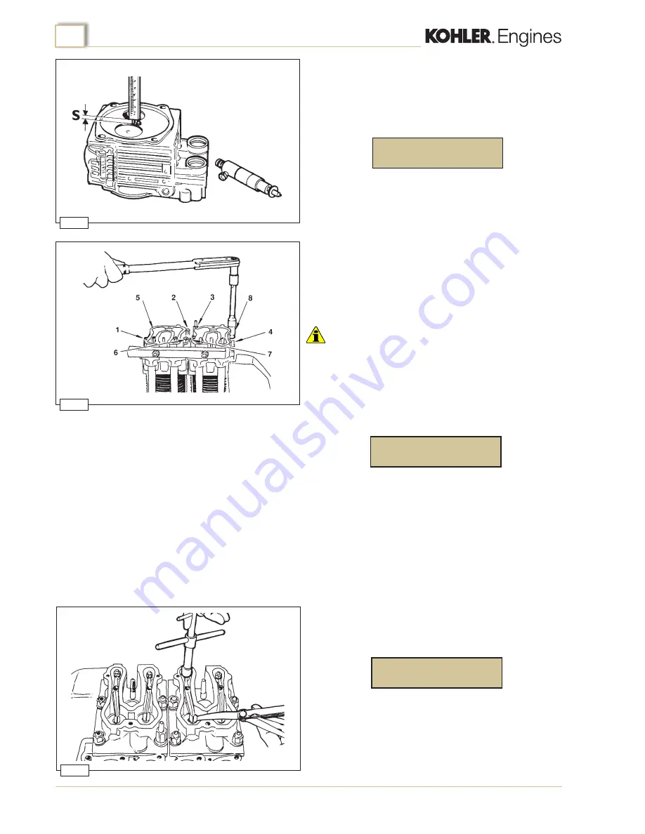
Checking injector protrusion
Before mounting the heads to the cylinders fit the injectors
into their housings and, after having secured them temporarily,
check the protrusion of the nozzles from the head faces (fig.77).
Protrusion
S
should be:
Cylinder heads
For checking and overhaul of the cylinder heads refer to page
19.
Fit the push rods and oil sealing O-rings on the cover pipes and
proceed to install the cylinder heads with the relative gaskets on
the facing surfaces.
Important
•
Make sure that the oil seal rings are correctly seated in the heads
to avoid the risk of oil leaks.
Align the heads using a metal bar or the exhaust manifold
(fig.78).
Following a cross pattern tighten the head nuts (fig.78) in
increments of 1 kgm until you reach the value:
This value is adjusted by inserting copper washers between the
injectors and the injector supporting faces on the heads (fig. 77).
Valve clearance
The clearance between valves and rockers with the engine cold
(fig.79) is:
This clearance is to be adjusted with the pistons at their
respective TDC compression positions.
intake/exhaust
KD425-2 Workshop Manual_cod. ED0053031750_
1° ed
_ rev.
00
Summary of Contents for KD425-2
Page 1: ...KD 425 2 WORKSHOP MANUAL...
Page 6: ...6 KD425 2 Workshop Manual_cod ED0053031750_1 ed_ rev 00...
Page 7: ...7 KD425 2 Workshop Manual_cod ED0053031750_1 ed_ rev 00...
Page 54: ...54 KD425 2 Workshop Manual_cod ED0053031750_1 ed_ rev 00...
Page 55: ...55 KD425 2 Workshop Manual_cod ED0053031750_1 ed_ rev 00...


