


-9-
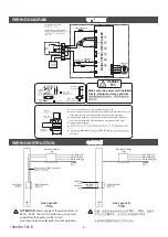
8. Take down the wiring cover plate. Insert the power cord
and 2 power lines of wall controller into the wire terminals.
Tighten the terminal screws and fix the lines. Finally, mount
the wiring cover plate. In line layout B, power line of wall
controller needn't be connected to wire box.
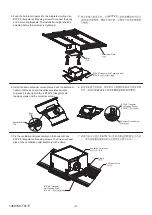
9. Put back and install the remaining plates. (Installation
finished)
8.
3
2
B
9.
(
)
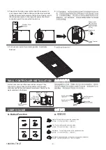
WALL CONTROLLER INSTALLATION
2
Power cord
L
N
Wiring Terminal
Wire Box Cover
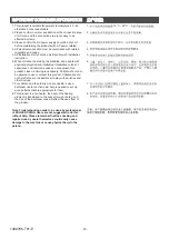
USER'S GUIDE
A. Button Function
A.
Heater: Turn on/off or switch to the heater mode.
/
"
"
"
"
Fan: Turn on/off or switch to the fan mode.
/
"
"
"
"
Ventilation
Turn on/off or switch to the ventilation mode.
/
"
"
"
"
Air Flow: Switch the air flow to fixed flow or swing flow (defaulted).
Power Line
Wall Controller
Wall Controller L
L
Wall Controller N
N
Screw
*2
ST4 10 Self
Tapping Screw
ST4 10
Base
Wall Controller
Back Cover
Power Line of
Wall Controller
(Line Layout A)
(
A)
Fix the back cover and the base with two screws. Then
connect two power lines of wall controller with the wall
controller and tighten with power line screws. Finally, fix the
wall controller on the frame.
1369766-T01-E


