Install Push Rods and Rocker Arms
NOTE: Push rods should always be installed in same
position as before disassembly.
1. Note mark or tag identifying push rod as either
intake or exhaust and cylinder 1 or 2. Dip ends of
push rods in engine oil and install, making sure that
each push rod ball seats in its hydraulic lifter socket.
2. Apply grease to contact surfaces of rocker arms and
rocker arm pivots. Install rocker arms and rocker arm
pivots on one cylinder head, and start screws.
3. Torque screws to 18.1 N·m (160 in. lb.).
4. Use a spanner wrench or rocker arm lifting tool, to lift
rocker arms and position push rods underneath.
5. Repeat above steps for remaining cylinder. Do not
interchange parts from cylinder heads.
6. Rotate crankshaft to check for free operation of
valve train. Check clearance between valve spring
coils at full lift. Minimum allowable clearance is 0.25
mm (0.010 in.).
Check Assembly
Rotate crankshaft a minimum of two revolutions to check
long block assembly and overall proper operation.
Install Spark Plugs
1. Check gap using wire feeler gauge. Adjust gap to
0.76 mm (0.030 in.).
2. Install plug into cylinder head.
3. Torque plug to 27 N·m (20 ft. lb.).
Install Ignition Modules
1. Rotate flywheel to position magnet away from
ignition module bosses.
2. CDI modules are installed with spark plug lead wire
from module always away from cylinder. On cylinder
1, single kill tab should be towards you. On cylinder
2, single kill tab should be away from you (in).
MDI modules are installed with flat side out/towards
you.
3. Install each ignition module to crankcase bosses.
Slide modules up as far away from flywheel as
possible and snug screws to hold them in position.
4. Rotate flywheel to position magnet directly under
one ignition module.
5. Insert a 0.25 mm (0.009 in.) flat feeler gauge
between magnet and ignition module. Loosen
screws enough to allow magnet to pull module down
against feeler gauge.
6. Torque screws to 4.0-6.2 N·m (35-55 in. lb.).
7. Repeat steps 4 through 6 for other ignition module.
8. Rotate flywheel back and forth checking for
clearance between magnet and ignition modules.
Make sure magnet does not strike modules. Check
gap with a feeler gauge and readjust if necessary.
Final air gap: 0.203/0.305 mm (0.008/0.012 in.).
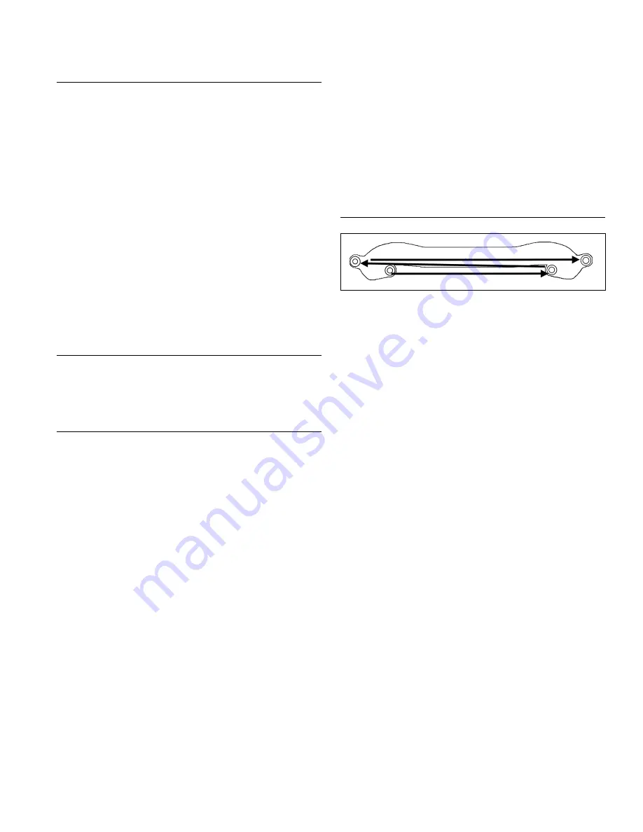
Install Intake Manifold
Torque Sequence
3
1
2
4
1. Install intake manifold and new gaskets (adhesive
side to manifold), with wiring harness attached, to
cylinder heads. Slide any wiring harness clips onto
appropriate bolts before installing. Make sure
gaskets are in proper orientation. Torque screws in
two stages, first to 7.4 N·m (66 in. lb.), then to 9.9
N·m (88 in. lb.), using sequence shown.
2. Connect each kill lead to tab terminal on each
ignition module.
3. If air cleaner support bracket was removed from
intake manifold reinstall it. Secure to top of intake
manifold with 2 screws. Torque screws to 9.9 N·m
(88 in. lb.).
Reassembly
59
24 690 37 Rev. B
KohlerEngines.com


